CG Drives & Automation 01-7491-01r0 Main Features 75
7.6.6 Wiring Alternating Master
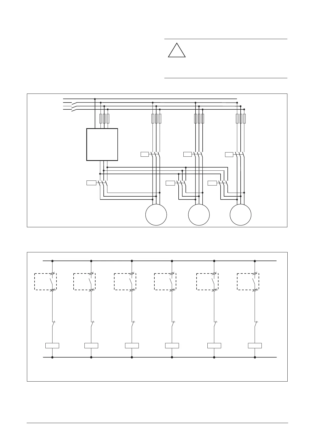
Fig. 85 and fig. 86 show the relay functions MasterPump1-6
and SlavePump1-6. The Master and Additional contactors
also interlock with each other to prevent dual powering of
the pump and damage to the inverter. (K1M/K1S, K2M/
K2S, K3M/K3S). Before running, the FDU will select a
pump to be Master, depending on the pump run times.
Fig. 85 Power connections for Alternating MASTER circuit with 3 pumps.
Fig. 86 Control connections for Alternating MASTER circuit with 3 pumps.
CAUTION!
The wiring for the Alternating Master
control needs special attention and
should be wired exactly as described
here, to avoid destructive short circuit
at the output of the inverter.
!
P1
3~
P2
3~
P3
3~
PE L1 L2 L3
UVW
FDU
PE
L1
L2
L3
K1S
K1M
K2M
K2S
K3S
K3M
(NG_50-PC-10_1)
K1S
B2:R1
Slave
Pump1
K1M
B1:R1
Master
Pump1
~
N
(NG_50-PC-11_3)
K2M
B1:R2
Master
Pump2
K2S
B2:R2
Slave
Pump2
K3M
B1:R3
Master
Pump3
K3S
B2:R3
Slave
Pump3
K1S
K1M
K2M
K2S
K3MK3S

 Loading...

