CG Drives & Automation 01-7491-01r0 Main Features 71
7.6 Pump function
7.6.1 Introduction
A maximum of 4 pumps can be controlled with the standard
AC drive.
If I/O Board options are installed, a maximum of 7 pumps
can be controlled. The I/O Board can also be used as a
general extended I/O.
The Pump Control function is used to control a number of
drives (pumps, fans, etc., with a maximum of 3 additional
drives per I/O-board connected) of which one is always
driven by the AC drive. Other names for these kind of
controllers are 'Cascade controller' or 'Hydrophore
controller'.
Depending on the flow, pressure or temperature, additional
pumps can be activated via the appropriate signals from the
output relays of the AC drive and/or the I/O Board. The
system is developed in such a way that one AC drive will be
the master of the system.
Select a relay on the control board or on an option board.
The relays are set to functions for controlling pumps. In the
pictures in this section, the relays are named R:Function,
e.g. R:SlavePump1, which means a relay on the control
board or on a option board set to function SlavePump1.
Fig. 77 Flow control with pump control option.
All additional pumps can be activated via an AC drive, soft
starter, Y
/ or D.O.L. switches.
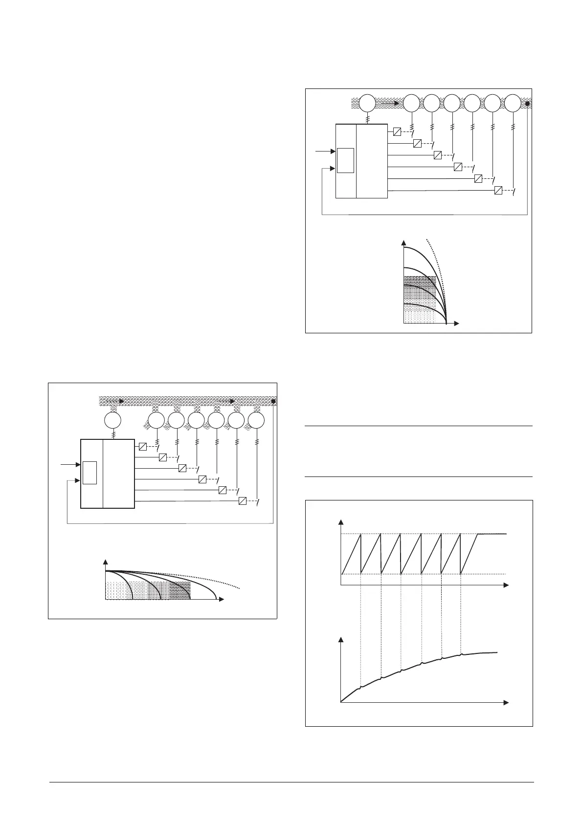
Fig. 78 Pressure control with pump control option.
Pumps in parallel will operate as a flow controller, See fig.
77.
Pumps in a series will operate as a pressure controller see fig.
78. The basic control principle is shown in fig. 79.
Fig. 79 Basic Control principle.
R:SlavePump3
R:SlavePump1
R:SlavePump2
R:SlavePump4
FDU
MASTER
P1 P2 P3 P4 P5 P6
AnIn
AnIn
Set FLOW
Feedback
FLOW
PM
PID
R:SlavePump5
R:SlavePump6
Pressure
Flow
Power
3
2
1
4
(50-PC-1_1)
NOTE: Read this instruction manual carefully
before commencing installation, connecting or
working with the AC drive with Pump Control
option.
R:SlavePump3
R:SlavePump1
R:SlavePump2
R:SlavePump4
FDU
MASTER
AnIn
AnIn
Set
PRESSURE
Feedback
PRESSURE
PID
R:SlavePump5
R:SlavePump6
P1 P2 P3 P4 P5 P6PM
Pressure
Flow
3
2
1
4
Power
(50-PC-2_1)
FLOW /
PRESSURE
Add pump
FREQUENCY (master pump P)
Stop pump
P1=on P2=on P3=on P4=on P5=on P6=on
P=on
TIM E
FLOW /
PRESSURE
(50-PC-3_1)

 Loading...

