CG Drives & Automation 01-7491-01r0 Control Connections 51
4.4 Connection example
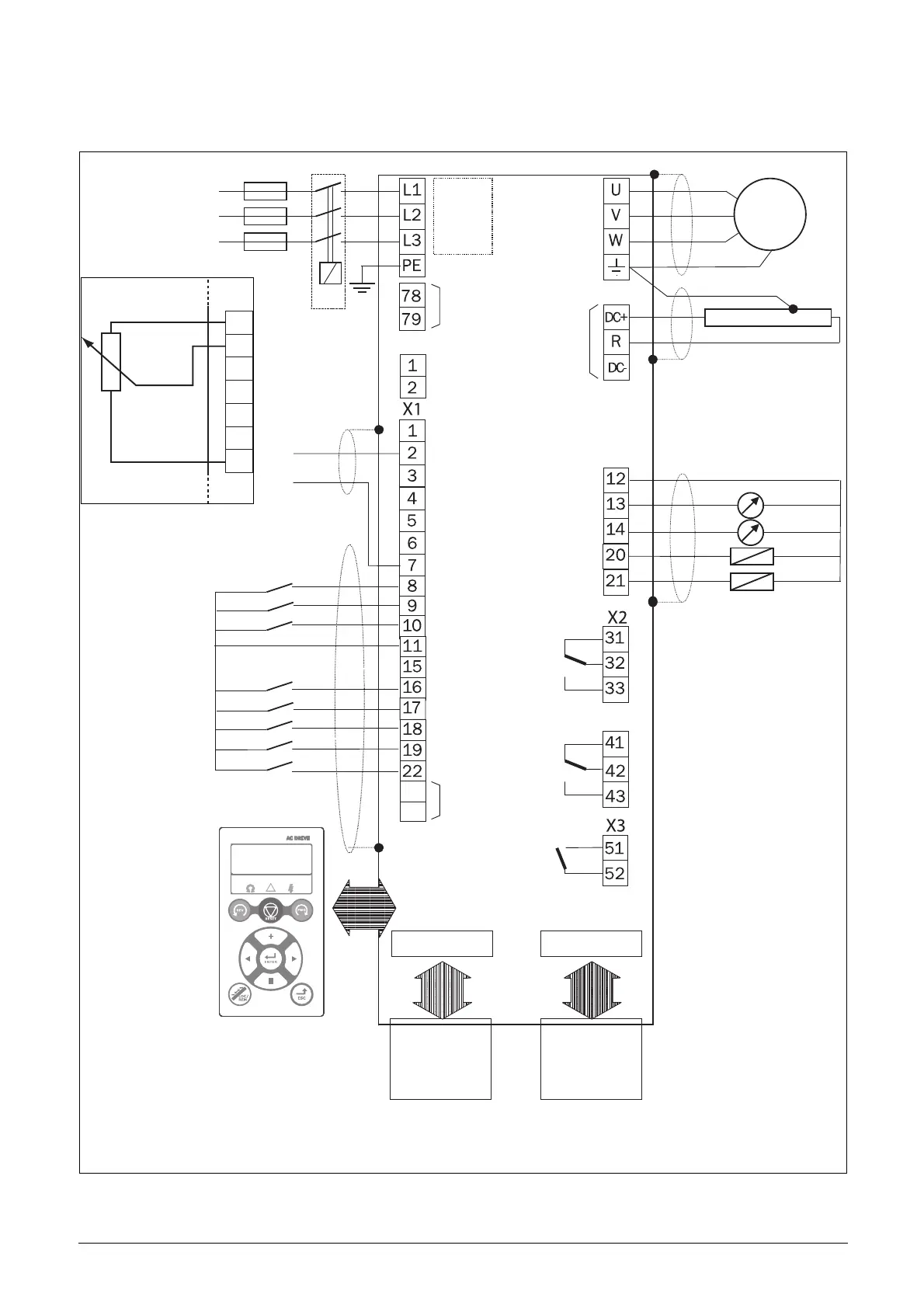
Fig. 57 gives an overall view of a AC drive connection example.
Fig. 57 Connection example.
EMC-
filter
+10 VDC
AnIn 1: Reference
AnIn 2
AnIn 3
AnIn 4
-10 VDC
Common
DigIn 1:RunL*
DigIn 2:RunR*
DigIn 3
+24 VDC
Common (Dig)
DigIn 4
DigIn 5
DigIn 6
DigIn 7
DigIn 8:Reset*
Common
AnOut 1
AnOut 2
DigOut 2
DigOut 1
Motor
Fieldbus option
Option board
Other options
0 - 10 V
4 - 20 mA
Alternative for
potentiometer
Optional
* Default setting
Relay 1
Relay 2
Relay 3
** The switch S1 is set to U
Comm. options
*** Optional terminals X1: 78 - 79 for connection of Motor-PTC on frame sizes B, C and D.
Optional ***
Motor PTC
Possible potentiometer value in range of 1 kΩ
to 10 kΩ (¼ Watt) linear, where we advice to use a
linear 1 kΩ / ¼ W type potentiometer for best control linearity.
control**
RS-485
- 0 V
+ 24 VDC SBS supply

 Loading...

