CG Drives & Automation 01-7491-01r0 175
11.6.5 Timers [650]
The Timer functions can be used as a delay timer or as an
interval with separate “on” and “off” times (alternate mode),
or as a way to prolong a signal (on-time mode). The selected
trigger signal starts the timer function, and the signal is
converted according to the mode settings, resulting in the
timer output signal (T1Q - T4Q). In “Delay” mode, the
output signal T1Q becomes high if the set delay time is
expired. See fig. 143.
In “Delay” mode, the activation of the timer output signal
will be delayed in comparison to the trigger signal. The
timer output signal is activated (high) when the set delay
time has expired. See fig. 143. The timer output signal will
however follow the trigger signal when this is deactivated
(low) again.
Fig. 143 Delay timer mode.
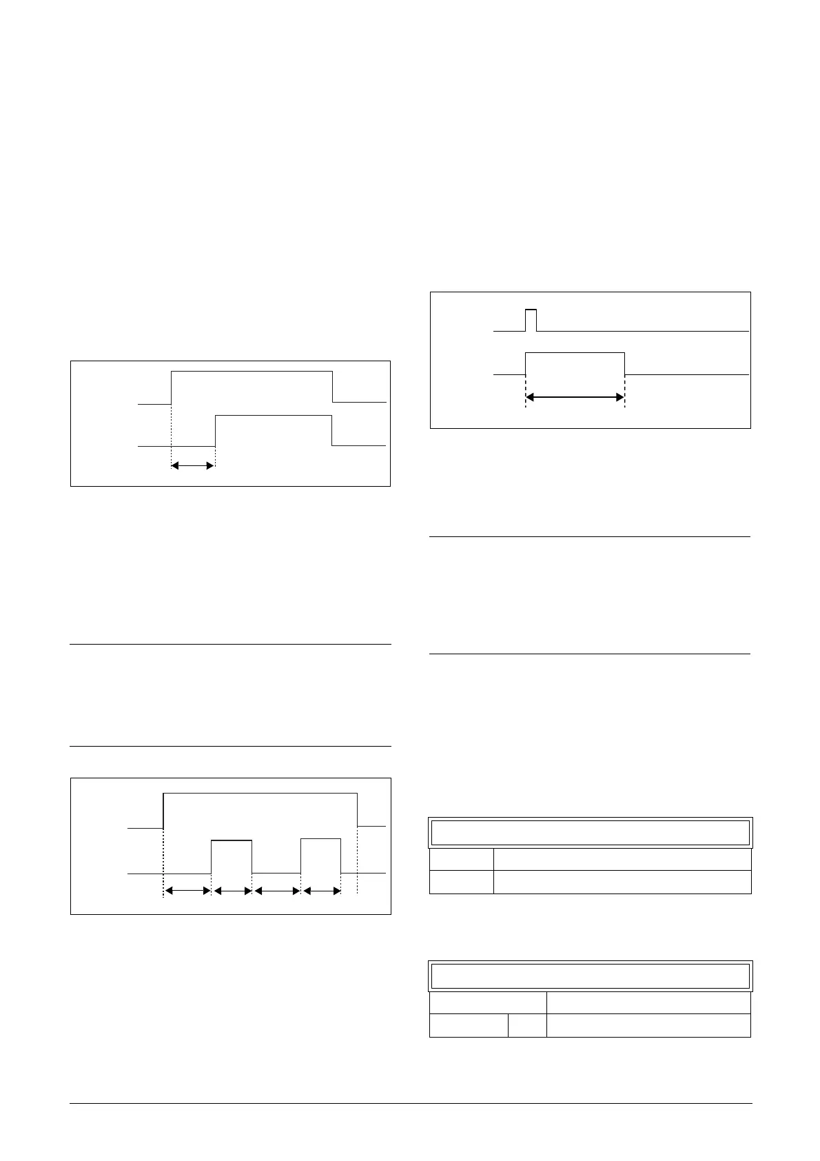
In alternate mode, the output signal T1Q will switch
automatically from high to low etc. according to the set
interval times “Timer1 T1” and “Timer 1 T2”. See fig. 144.
The output signal can be programmed to the digital or relay
outputs used in logic functions [600] or as a
virtual connection source [560].
Fig. 144 Alternative timer mode
The function of the “On-time” mode is to extend an
activated (high) timer output signal in comparison to the
trigger signal. See Fig. 145.
• Output goes high when in signal goes high (positive edge
trigged)
•Output stays high for configured time.
• If new positive edge is detected during configured on-
time the elapsed time is reset.
• In case the in signal stays high longer than configured
time output is kept high as long as in signal is active.
Fig. 145 On-time timer mode.
The timer output signals (T1Q - T4Q) can be programmed
to the relay outputs used in logic functions [620], or be used
as a virtual connection source [560].
Timer 1 [651]
Parameter group for Timer 1.
Timer 1 Trig [6511]
Selection of the Timer input trigger signal
Timer 1 can be activated by a high signal on a DigIn that is
set to Timer 1 or via a virtual destination [560].
Timer 1 Mode [6512]
Selection of mode of operation for Timer 1.
NOTE: The actual timers are common for all
parameter sets. If the actual set is changed, the timer
functionality [641] to [645] will change according set
settings but the timer value will stay unchanged. So
initialization of the timer might differ for a set change
compared to normal triggering of a timer.
Timer1 Trig
T1Q
Timer1 delay
Timer1 T2
Timer1 T1
Timer1 Trig
T1Q
Timer1 T2
Timer1 T1
NOTE: The actual timers are common for all
parameter sets. If the actual parameter set is
changed, the timer functionality will change
according to the settings, but the timer value will stay
unchanged. So initialisation of the timer might differ
for a set change compared to normal triggering of a
timer.
6511 Timer1 Trig
Default: Off
Selection: Same as in menu DigOut 1
[541].
6512 Timer1 Mode
Default: Off
Off 0 Timer is disabled

 Loading...

