CG Drives & Automation 01-7491-01r0 Control Connections 47
4. Control Connections
4.1 Control board
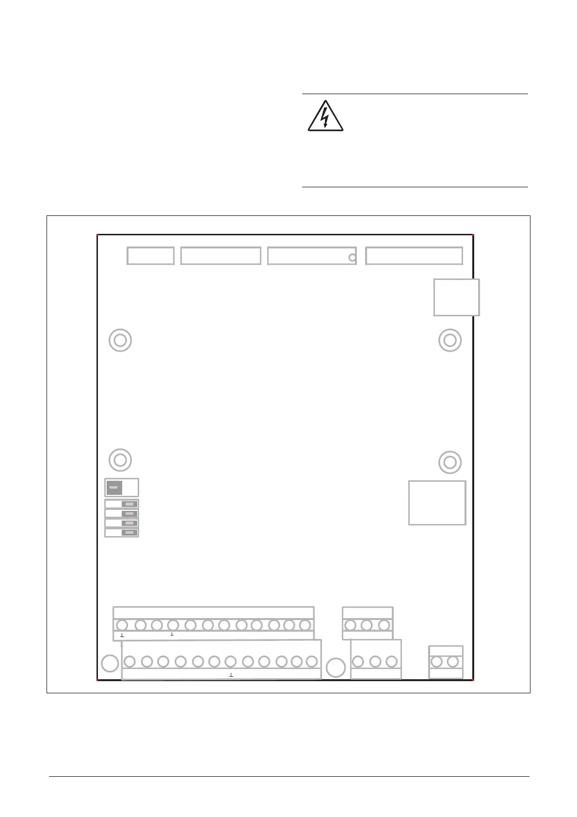
Fig. 56 shows the layout of the control board which is where
the parts most important to the user are located. Although
the control board is galvanically isolated from the mains, for
safety reasons do not make changes while the mains supply
is on!
Fig. 56 Control board layout.
WARNING!
Always switch off the mains voltage and
wait at least 7 minutes to allow the DC
capacitors to discharge before connecting
the control signals or changing position of any
switches. If the option External supply is used, switch
of the mains to the option. This is done to prevent
damage on the control board.
X8
X2
X3
X1
S1
X5X4 X6
X7
U
I
S2
S3
S4
S5
1
12
22
11
41
42 43
31 32
33
51
52
23 4 567 8 910
13 14 15 16 17 18 19 20 21
AO1
AO2
DI4
DI5
DI6 DI7
DO1
DO2
DI8
+24VDI3
DI2
DI1-10V
AI4
AI3AI2
AI1+10V
NC
NC
NO
NO
NO
C
C
C
R01
R02
R03
X11
A+
B-
OFF
PE
Relay outputs
Control signals
AnIn jumpers
Option
Control
Panel
Communication
Standby supply
Termination switch, RS485

 Loading...

