CG Drives & Automation 01-7491-01r0 Control Connections 53
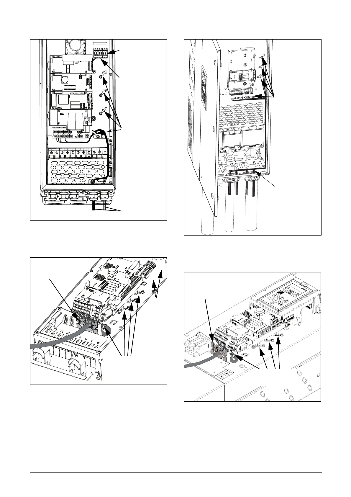
Fig. 61 Connecting the control signals, FDU model 061 to
074, frame size D and model 69-033 to 69-058
frame size D(69).
Fig. 62 Connecting the control signals, FDU model 48-072 to
48-105 frame size D2 and model 69-033 to 69-058
frame size D2(69).
Fig. 63 Connecting the control signals, FDU model 48-090 to
295 and FDU model 69-82 to 200, frame size E, F
and F69 (principle drawing).
Fig. 64 Connecting the control signals, FDU model 48-142 to
48-365 frame size E2, F2 and FA2 (principle
drawing).
Control signals
Terminal 78 & 79
see table 25
Screen clamps
for signal cables
Terminal A- & B+
see table 25
L1 L2 L3 DC- DC+ R U V W
78 79, A- B+
Feed-through of
signal cables
Screen clamps
for signal cables
See
table 25
Control signals
Screen clamps
for signal cables
Screen clamps
for signal cables
Feed-through of
signal cables

 Loading...

