Cerabar PMP21 IO-Link System integration
Endress+Hauser 25
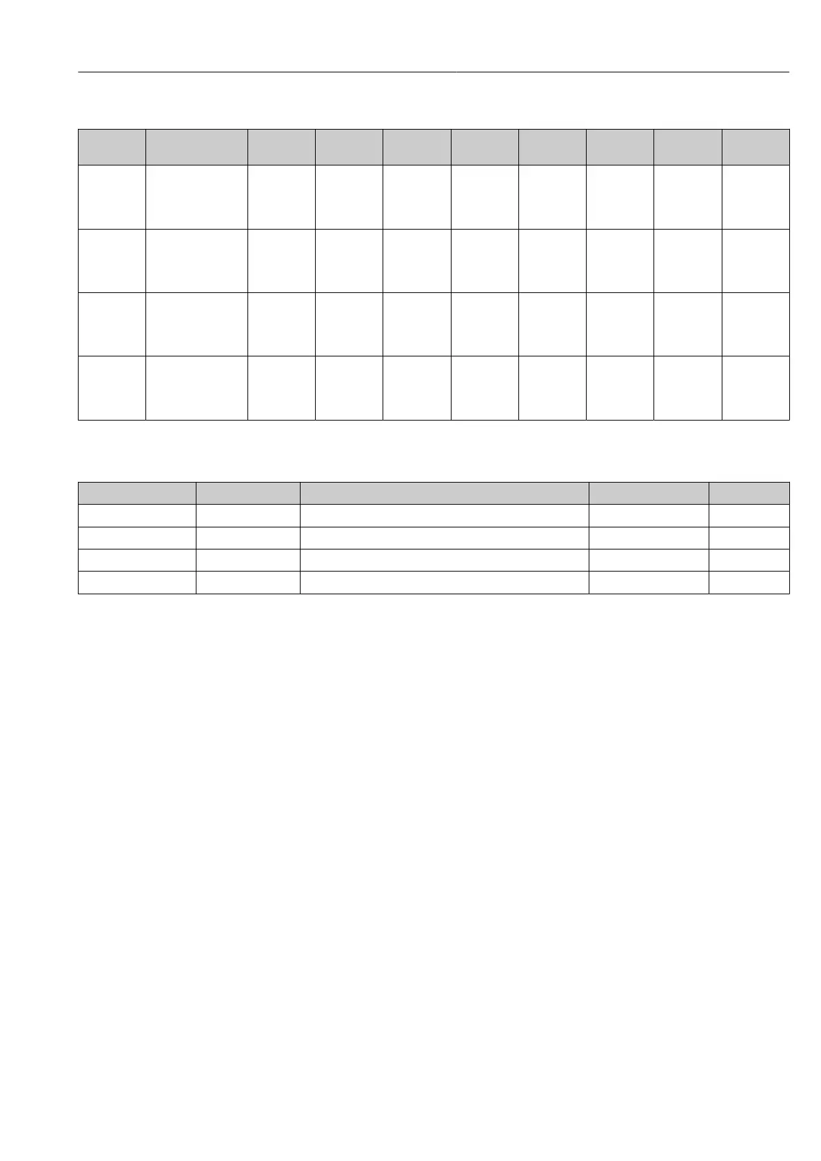
Measurement Data Information
ISDU (dec) Subindex Description ISDU (hex) Size (byte) Data type Access Default
value
Value
range
Data
storage
16512 1 MDC
Descriptor -
Pressure.Lo
wer Value
0x4080 4 Float32T r 0 - No
16512 2 MDC
Descriptor -
Pressure.Up
per Value
0x4080 4 Float32T r 0 - No
16512 3 MDC
Descriptor -
Pressure.Un
it Code
0x4080 2 UintegerT r 1130 (Pa) - No
16512 4 MDC
Descriptor -
Pressure.Sca
le
0x4080 1 IntegerT r 0 - No
8.2.3 System commands
ISDU (dec) Subindex Description ISDU (hex) Access
2 65 Teach SP1 0x0002 w
2 66 Teach SP2 0x0002 w
2 130 Reset to factory settings (RES) 0x0002 w
2 131 Back-To-Box 0x0002 w
8.2.4 Switching signals
The switching signals offer a simple way of monitoring the measured values for limit
violations.
Each switching signal is clearly assigned to a process value and provides a status. This
status is transmitted with the process data (process data link). Its switching behavior must
be configured using the configuration parameters of a "Switching Signal Channel" (SSC). In
addition to manual configuration for switch points SP1 and SP2, a teach mechanism is
available in the "Teach" menu. This mechanism writes the current process value to the
selected SSC via a system command. The following section illustrates the different
behaviors of the modes available for selection. The "Logic" parameter is always "High active"
in these cases. If the logic is supposed to be inverted, the "Logic" parameter can be set to
"Low active"(→ 33).
Single Point Mode
SP2 is not used in this mode.