Electrical connection Ecograph T, RSG35
14 Endress+Hauser
shielded and the shield forms as complete a cover as possible. A shielded line must be used
for sensor lines that are longer than 30 m. A shield coverage of 90% is ideal. In addition,
make sure not to cross sensor lines and communication lines when routing them. Connect
the shield as often as possible to the reference ground to ensure optimum EMC protection
for the different communication protocols and the connected sensors.
To comply with requirements, three different types of shielding are possible:
• Shielding at both ends
• Shielding at one end on the supply side with capacitance termination at the device
• Shielding at one end on the supply side
Experience shows that the best results with regard to EMC are achieved in most cases in
installations with one-sided shielding on the supply side (without capacitance termination
at the device). Appropriate internal device wiring measures must be taken to allow
unrestricted operation when EMC interference is present. These measures have been
taken into account for this device. Operation in the event of disturbance variables as per
NAMUR NE21 is thus guaranteed.
Where applicable, national installation regulations and guidelines must be observed
during the installation! Where there are large differences in potential between the
individual grounding points, only one point of the shielding is connected directly with the
reference ground.
If the shielding of the cable is grounded at more than one point in systems without
potential matching, mains frequency equalizing currents can occur. These can damage
the signal cable or significantly impact signal transmission. In such cases the shielding
of the signal cable is to be grounded on one side only, i.e. it may not be connected to
the ground terminal of the housing. The shield that is not connected should be
insulated!
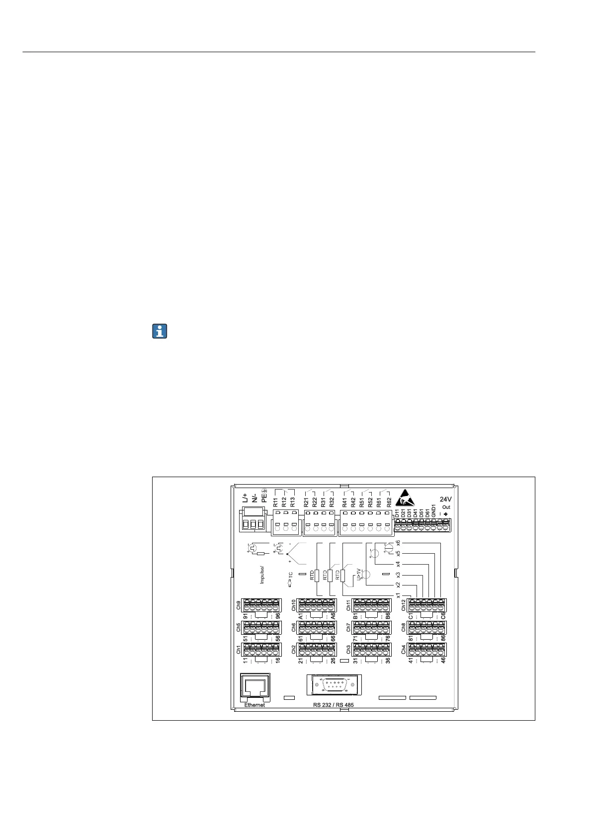
6.3 Connecting the measuring device
6.3.1 Terminal assignment on the rear of the device
A0019304
3 Terminals on the rear of the device

 Loading...