Electrical connection Ecograph T, RSG35
20 Endress+Hauser
Meaning of the LEDs
Beneath the Ethernet connection (see rear of device) there are two light emitting diodes
which indicate the status of the Ethernet interface.
• Yellow LED: link signal; is lit when the device is connected to a network. If this LED is not
illuminated then communication is impossible.
• Green LED: Tx/Rx; flashes irregularly if the device is transmitting or receiving data.
6.3.10 Option: Ethernet Modbus TCP slave
The Modbus TCP interface is used to connect to higher-ranking SCADA systems (Modbus
master) to transmit all measured values and process values. Up to 12 analog inputs and 6
digital inputs can be transmitted via Modbus and stored in the device. Form a physical
point of view, the Modbus TCP interface is identical to the Ethernet interface.
6.3.11 Option: Modbus RTU slave
The Modbus RTU (RS485) interface is galvanically isolated (testing voltage: 500 V) and is
used to connect to higher-ranking systems to transmit all measured values and process
values. Up to 12 analog inputs and 6 digital inputs can be transmitted via Modbus and
stored in the device. Connection is via the combined RS232/RS485 interface.
Modbus TCP and Modbus RTU cannot be used at the same time.
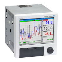
6.3.12 Connections at front of device
A0019501
6 Front of device with open flap
1 Navigator
2 LED at SD slot. Orange LED lights up or flashes when the device writes to or reads from the SD card.
3 Slot for SD card
4 USB B socket "Function" e.g. to connect to PC or laptop
5 Green LED lit: power supply present
6 USB A socket "Host" e.g. for USB memory stick or external keyboard
7-12 For a description of the displays, see the "Operability" section
 Loading...