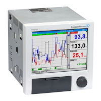
Ecograph T, RSG35 Technical data
Endress+Hauser 67
Converter resolution
24 bit
Totalization
The interim, daily, monthly and yearly value and the total value can be determined (13-
digit, 64 bit).
Analysis
Recording of quantity/operating time (standard function), also a min/max/median
analysis within the set time frame.
Digital inputs
Input level To IEC 61131-2: logical “0" (corresponds to -3 to +5 V), activation with logical "1"
(corresponds to +12 to +30 V)
Input frequency max. 25 Hz
Pulse length Min. 20 ms (pulse counter)
Pulse length Min. 100 ms (control input, messages, operating time)
Input current max. 2 mA
Input voltage Max. 30 V
Selectable functions
• Functions of the digital input: control input, ON/OFF message, pulse counter (13-digit,
64 bit), operating time, message+operating time, quantity from time, Modbus slave.
• Functions of the control input: start recording, screen saver on, lock setup, time
synchronization, limit monitoring on/off, lock keyboard/navigator, start/stop analysis.
15.3 Output
Auxiliary voltage output The auxiliary voltage output can be used for loop power supply or to control the digital
inputs. The auxiliary voltage is short-circuit proof and galvanically isolated.
Output voltage 24 V
DC
±15%
Output current Max. 250 mA
Galvanic isolation All inputs and outputs are galvanically isolated from each other and designed for the
following testing voltages:
Relay Digital
in
Analog
in
Ethernet RS232/RS485 USB Auxiliary
voltage output
Relay 500
V
DC
2 kV
DC
2 kV
DC
2 kV
DC
2 kV
DC
2 kV
DC
2 kV
DC
Digital in 2 kV
DC
Galvanic
ally
connecte
d
500 V
DC
500 V
DC
500 V
DC
500 V
DC
500 V
DC
Analog in 2 kV
DC
500 V
DC
500 V
DC
500 V
DC
500 V
DC
500 V
DC
500 V
DC
Ethernet 2 kV
DC
500 V
DC
500 V
DC
- 500 V
DC
500 V
DC
500 V
DC
RS232/RS485 2 kV
DC
500 V
DC
500 V
DC
500 V
DC
- 500 V
DC
500 V
DC

 Loading...