Electrical connection Ecograph T, RSG35
18 Endress+Hauser
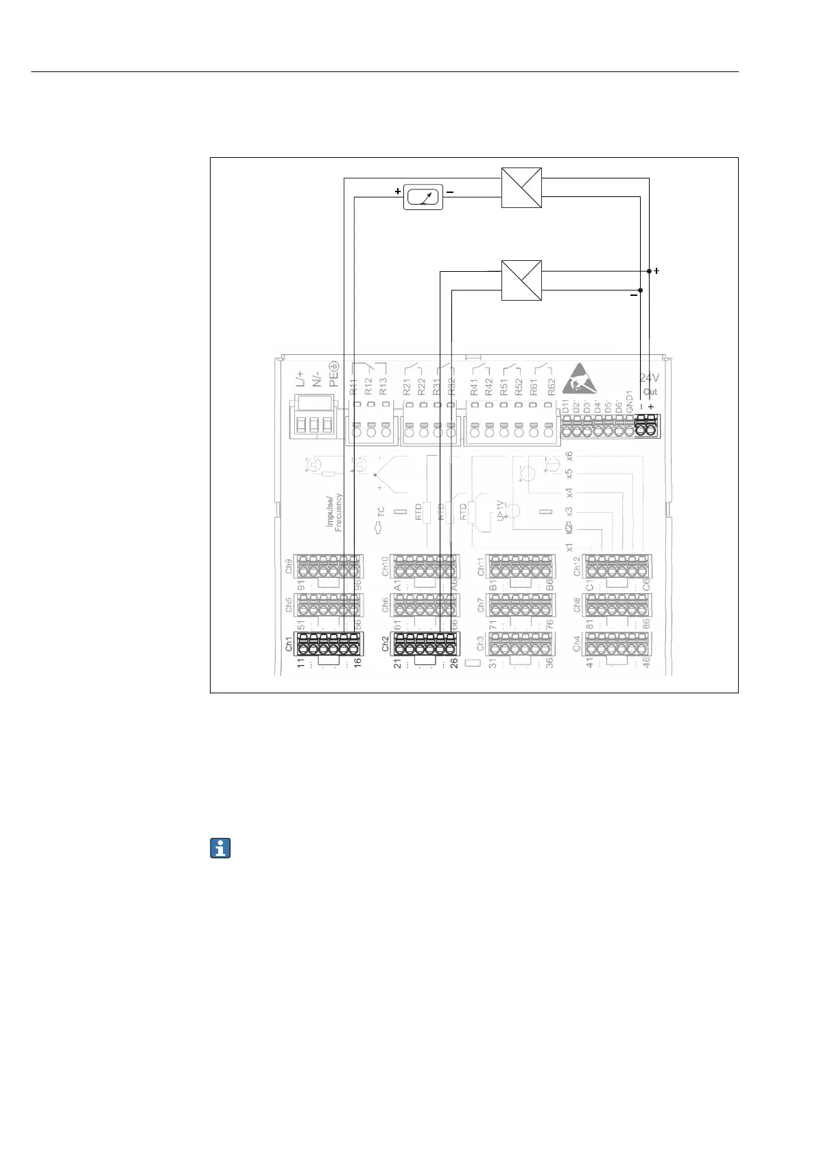
6.3.7 Connection example: Auxiliary voltage output as transmitter
power supply for 4-wire sensors
Frequency
_
+
+
_
Out: max. 250 mA
+
-
Y
+
-
I
24V
+
-
Y
+
-
I
24V
1
2
3
A0020260
5 Connecting auxiliary voltage output when using as a transmitter power supply for 4-wire sensors in the
current measuring range. (When connecting channel CH3-12, see pin assignment CH1-2.)
1 Sensor 1 (e.g. temperature switch TTR31 from Endress+Hauser)
2 Sensor 2
3 External indicator (optional) (e.g. RIA16 from Endress+Hauser)
6.3.8 Option: RS232/RS485 interface (rear of device)
Use shielded signal lines for serial interfaces!
A combined RS232/RS485 connection is available on a shielded SUB D9 socket at the rear
of the device. This can be used for data transfer and to connect a modem. For
communication via modem, we recommend an industrial modem with a watchdog
function.
 Loading...