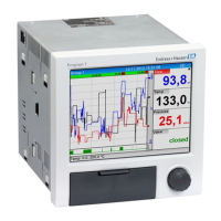
Ecograph T, RSG35 Table of contents
Endress+Hauser 3
Table of contents
1 Document information .............. 6
1.1 Document function ..................... 6
1.2 Symbols used .......................... 6
1.2.1 Safety symbols .................. 6
1.2.2 Electrical symbols ................ 6
1.2.3 Symbols for certain types of
information .................... 7
1.2.4 Symbols in graphics ............... 7
1.3 Terminology .......................... 7
1.4 Registered trademarks ................... 7
2 Basic safety instructions ............ 8
2.1 Requirements concerning the staff .......... 8
2.2 Designated use ........................ 8
2.3 Workplace safety ....................... 8
2.4 Operational safety ...................... 8
2.5 Product safety ......................... 9
2.6 Safety information for table version (option) ... 9
2.7 IT security ............................ 9
3 Product description ................. 9
3.1 Product design ......................... 9
4 Incoming acceptance and product
identification ..................... 10
4.1 Incoming acceptance ................... 10
4.2 Scope of delivery ...................... 10
4.3 Product identification ................... 10
4.3.1 Nameplate .................... 10
4.4 Storage and transport .................. 11
5 Installation ....................... 11
5.1 Mounting requirements ................. 11
5.1.1 Installation dimensions ........... 11
5.2 Mounting the measuring device ........... 11
5.3 Post-mounting check ................... 12
6 Electrical connection .............. 13
6.1 Connection conditions .................. 13
6.2 Connection instructions ................. 13
6.2.1 Cable specification ............... 13
6.3 Connecting the measuring device .......... 14
6.3.1 Terminal assignment on the rear of
the device ..................... 14
6.3.2 Supply voltage .................. 15
6.3.3 Relays ........................ 15
6.3.4 Digital inputs; auxiliary voltage
output ........................ 15
6.3.5 Analog inputs .................. 16
6.3.6 Connection example: Auxiliary
voltage output as transmitter power
supply for 2-wire sensors .......... 17
6.3.7 Connection example: Auxiliary
voltage output as transmitter power
supply for 4-wire sensors .......... 18
6.3.8 Option: RS232/RS485 interface (rear
of device) ..................... 18
6.3.9 Ethernet connection (rear of
device) ....................... 19
6.3.10 Option: Ethernet Modbus TCP slave .. 20
6.3.11 Option: Modbus RTU slave ......... 20
6.3.12 Connections at front of device ...... 20
6.4 Post-connection check .................. 22
7 Operation options ................. 23
7.1 Overview of operation options ............ 23
7.2 Structure and function of the operating
menu .............................. 23
7.2.1 Operating menu for operators and
maintenance personnel ........... 23
7.2.2 Operating menu for experts ........ 24
7.2.3 Submenus and users ............. 24
7.3 Measured value display and operating
elements ............................ 26
7.4 Display representation of symbols used in
operation ........................... 27
7.4.1 Symbols in operating menus ....... 28
7.4.2 Symbols in the event logbook ....... 28
7.5 Entering text and numbers (virtual
keyboard) ........................... 28
7.6 Channel color assignment ............... 29
7.7 Access to the operating menu via the local
display ............................. 29
7.8 Device access via operating tools .......... 29
7.8.1 Field Data Manager (FDM) analysis
software (SQL database support) .... 29
7.8.2 Web server .................... 30
7.8.3 OPC server (optional) ............ 30
7.8.4 FieldCare/DeviceCare configuration
software (included in the delivery) ... 30
8 System integration ................ 31
8.1 Integrating the measuring device in the
system ............................. 31
8.1.1 General notes .................. 31
8.1.2 Ethernet ...................... 31
8.1.3 Modbus RTU/TCP slave ........... 31
9 Commissioning .................... 32
9.1 Function check ....................... 32
9.2 Switching on the measuring device ......... 32
9.3 Setting the operating language ............ 32

 Loading...