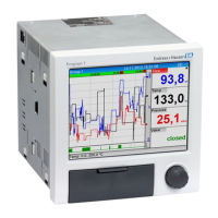
Ecograph T, RSG35 Operation options
Endress+Hauser 25
User role Typical tasks Menu Content/meaning
Fault elimination:
• Diagnosing and eliminating process errors.
• Interpretation of device error messages and
correcting associated errors.
"Diagnostics" Contains all parameters for detecting and analyzing
errors:
• Diagnosis list
All diagnosis messages are listed in chronological
order.
• Event logbook
Events such as limit value violations and power
failures are listed in chronological order.
• Device information
Displays important device information (e.g. serial
number, firmware version, device options for
hardware and software, memory information, etc.).
• Measured values
Display of current measured values of device.
• Outputs
Displays the current status of the outputs e.g. switch
status of relay outputs.
• Simulation
Various functions/signals can be simulated for test
purposes here.
Note: In Simulation mode, normal recording of the
measured values is interrupted and the intervention
is logged in the event log.
• Initialize modem
Initializes the modem connected to the serial
interface (for automatic call answering).
Expert Tasks that require detailed knowledge of the
function of the device:
• Commissioning measurements under difficult
conditions.
• Optimal adaptation of the measurement to
difficult conditions.
• Detailed configuration of the communication
interface.
• Error diagnostics in difficult cases.
"Expert" Contains all parameters of the device (including those
that are already in one of the other menus). The expert
menu is protected by a code. Factory setting: 0000. This
menu is structured according to the function blocks of
the device:
• "System" submenu
Contains all higher-order device parameters that do
not concern the measurement or measured value
communication.
• "Inputs" submenu
Contains all parameters for configuring the analog
and digital inputs.
• "Output" submenu
Contains all parameters for configuring the outputs
(e.g. relays).
• "Communication" submenu
Contains all parameters for configuring the
communication interfaces.
• "Application" submenu
Contains all parameters for configuring application-
specific settings (e.g. group settings, limit values
etc.).
• "Diagnostics" submenu
Contains all parameters needed to detect and
analyze operational errors.

 Loading...