Mounting Levelflex FMP51, FMP52, FMP54 FOUNDATION Fieldbus
26 Endress+Hauser
6.1.3 Notes on the mechanical load of the probe
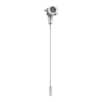
Tensile load limit of rope probes
Sensor Feature 060 Probe Tensile load limit [kN]
FMP51 LA, LB
MB, MD
Rope 4mm (1/6") 316 5
FMP52 OA, OB, OC, OD Rope 4mm (1/6") PFA>316 2
FMP54 LA, LB Rope 4mm (1/6") 316 10
Bending strength of rod probes
Sensor Feature 060 Probe Bending strength [Nm]
FMP51 AA, AB Rod 8mm (1/3") 316L 10
AC, AD Rod 12mm (1/2") 316L 30
AL, AM Rod 12mm (1/2") AlloyC 30
BA, BB, BC, BD Rod 16mm (0.63") 316L divisible 30
FMP52 CA, CB Rod 16mm (0.63") PFA>316L 30
FMP54 AE, AF Rod 16mm (0.63") 316L 30
BA, BB, BC, BD Rod 16mm (0.63") 316L divisible 30
Bending load (torque) through fluid flow
The formula for calculating the bending torque M impacting on the probe:
M = c
w
⋅ ρ/2 ⋅ v
2
⋅ d ⋅ L ⋅ (L
N
- 0.5 ⋅ L)
with:
c
w
: Friction factor
ρ [kg/m
3
]: Density of the medium
v [m/s]: Velocity of the medium perpendicular to the probe rod
d [m]: Diameter of the probe rod
L [m]: Level
LN [m]: Probe length
Calculation example
A0014175
Friction factor c
w
0,9 (on the assumption of a turbulent current - high
Reynolds number)
Density ρ [kg/m
3
] 1000 (e.g. water)
Probe diameter d [m] 0,008
L = L
N
(worst case)
 Loading...


