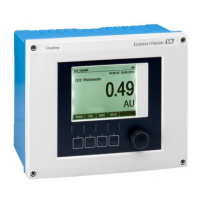
Electrical connection Liquiline CM44P
40 Endress+Hauser
Sensor Cable color PEM terminal Assignment
OUSBT66 BN P+ Lamp voltage +
BN S+ Recording lamp voltage +
BK P- Lamp voltage -
BK S- Recording lamp voltage -
RD A (1) Sensor +
OG C(1) Sensor -
TP SH (1) Shield
1) OUSAF12
2) OUSAF11
Memosens connection via M12 plug-in connection (field device only)
85 86
85
1
2
86
97 88 8798
Sensor 1
PK
GY
GN
YE
BN
WH
1
A0018019
47 M12 plug-in connection (e.g.
at sensor module)
1 Sensor cable with M12
connector
A0018021
48 M12 assignment Top:
socket Bottom: connector
(top view in each case)
1 PK (24 V)
2 GY (Ground 24 V)
3 BN (3 V)
4 WH (Ground 3 V)
5 GN (Memosens)
6 YE (Memosens)
7,
NC
Not connected
Device versions with a pre-installed
M12 socket are ready-wired upon
delivery.
Version without a pre-installed M12
socket
1. Insert an M12 socket
(accessory) into a suitable
opening in the base of the
housing.
2. Connect the cable to a
Memosens terminal as per the
wiring diagram.
Connecting the sensor
‣
Plug the connector of the sensor
cable (→ 47item 1) directly into
the M12 socket.
Please note the following:
• The internal device wiring is always
the same regardless of what kind of
sensor you connect to the M12
socket (plug&play).
• The signal or power supply cables
are assigned in the sensor head in
such a way that the PK and GY
power supply cables are either used
(e.g. optical sensors) or not (e.g. pH
or ORP sensors).
6.4 Connecting additional inputs, outputs or relays
L
WARNING
Module not covered
No shock protection. Danger of electric shock!
‣
Change or extend the hardware: always fill the slots from left to right. Do not leave any
gaps.
‣
If all of the slots are not occupied: always insert a dummy cover or end cover in the slot
to the right of the last module(→ 2, 10). This ensures that the unit is shock-
protected.
‣
Always ensure shock protection is guaranteed particularly in the case of relay modules
(2R, 4R, AOR).
The terminal strip (cabinet unit) is used to connect the cable shields.

 Loading...