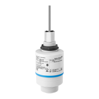
Micropilot FMR60B PROFINET with Ethernet-APL
Endress+Hauser 25
Integrated antenna, PEEK 20 mm / 3/4", α 14 °
W = D × 0.26 D W
5 m (16 ft) 1.23 m (4.04 ft)
10 m (33 ft) 2.46 m (8.07 ft)
Integrated antenna, PEEK 40 mm / 1-1/2", α = 8 °
W = D × 0.14 D W
5 m (16 ft) 0.70 m (2.29 ft)
10 m (33 ft) 1.40 m (4.58 ft)
15 m (49 ft) 2.09 m (6.87 ft)
20 m (66 ft) 2.79 m (9.16 ft)
22 m (72.18 ft) 3.08 m (10.10 ft)
Special mounting
instructions
Measurement through a ball valve
A0034564
• Measurements can be performed through an open full bore ball valve without any problems.
• At the transitions, no gap exceeding 1 mm (0.04 in) may be left.
• Opening diameter of ball valve must always correspond to the pipe diameter; avoid edges and
constrictions.
External measurement through plastic cover or dielectric windows
• Dielectric constant of medium: ε
r
≥ 10
• The distance from the tip of the antenna to the tank should be approx. 100 mm (4 in).
• Avoid installation positions where condensate or buildup can form between the antenna and the
vessel
• In the case of outdoor installations, ensure that the area between the antenna and the tank is
protected from the weather
• Do not install any fittings or attachments between the antenna and the tank that could reflect the
signal
The thickness of the tank ceiling or the dielectric window depends on the ε
r
of the material.

 Loading...
