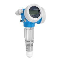
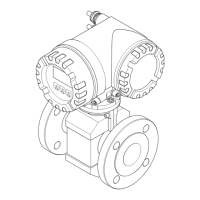
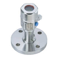
Micropilot FMR62
30 Endress+Hauser
Beam diameter W as a function of beam angle α and distance D.
Integrated, PEEK 20 mm / 3/4" antenna, α 14 °
W = D × 0.25
Integrated, PEEK 40 mm / 1-1/2" antenna, α 8 °
W = D × 0.14
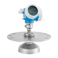
PTFE cladded, flush mount 50 mm (2 in) antenna, α 7 °
W = D × 0.12
PTFE cladded, flush mount 80 mm (3 in) antenna, α 3 °
W = D × 0.05
Measurement through a ball valve
A0034564
• Measurements can be performed through an open full bore ball valve without any problems.
• At the transitions, no gap may be left exceeding 1 mm (0.04 in).
• Diameter of opening of ball valve must always be equivalent to pipe diameter; avoid edges and
constrictions.
External measurement through plastic cover or dielectric windows
• Dielectric constant of medium: ε
r
≥ 10
• The distance from the tip of the antenna to the tank should be approx. 100 mm (4 in).
• If possible, avoid installation positions in which condensate or buildup can form between the
antenna and the vessel.
• In the case of outdoor installations, ensure that the area between the antenna and the tank is
protected from the weather.
• Do not install any fittings or attachments between the antenna and the tank that could reflect the
signal.
Suitable thickness of tank roof or window
Material PE PTFE PP Perspex
ε
r
(Dielectric constant of
medium)
2.3 2.1 2.3 3.1
Optimum thickness 1.25 mm
(0.049 in)
1)
1.3 mm
(0.051)
1)
1.25 mm
(0.049 in)
1)
1.07 mm
(0.042 in)
1)
1) or an integer that is a multiple of this value; it should be noted here that the microwave transparency
decreases significantly with increasing window thickness.
 Loading...
