65
10 Profibus Interface
10.1 FCYP Module
In the simplest case, a complete measuring point consists of the Mycom CLM 152 with the
FCYP module (see chapter 4, figure 4.13), a bus coupler, a PLC or a PC with the operating
program Commuwin II and a PROFIBUS PA terminating resistor.
The maximum number of transmitters in one bus segment is determined by their current
consumption, the power of the bus coupler and the required bus length (refer to TI 260F/
00/en for details).
Normally, up to 32 Mycom CLM 152 units can be operated in one bus segment in the
case of non-Ex applications.
10.2 Bus Cable
Shielded, twisted-pair cable should preferably be used for new installations (e.g. Belden
3097A, Siemens 6xV 1830-5AH10). The FISCO model (explosion protection) prescribes
the following specifications:
Loop impedance (DC) 14 to 150 W/km
Inductance per unit length 0.4 to 1 mH/km
Capacitance per unit length 80 to 200 nF/km
Please refer to TI 260F/00/en Project planning notes for Profibus PA and the PROFIBUS PA
specification for information on set-up and grounding of the network.
Caution!
Multiple grounding of the protective shield in explosion protection applications is
only permissible in special cases.
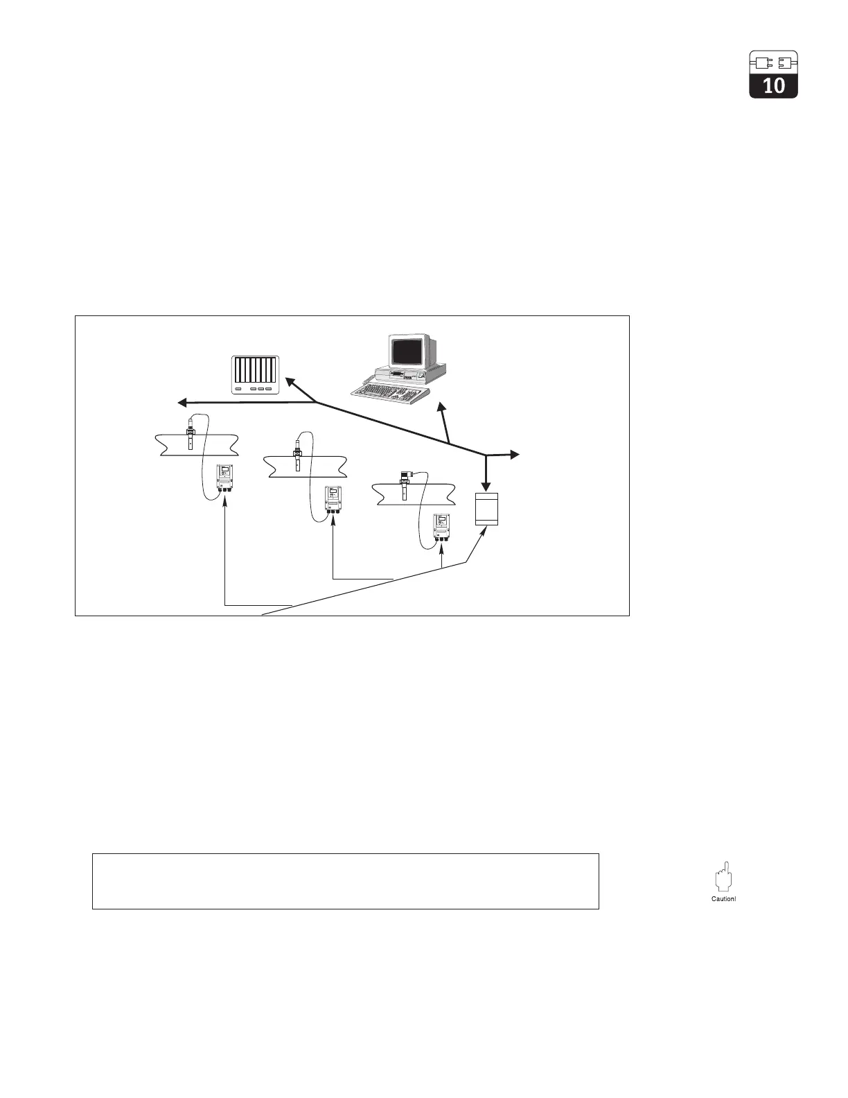
Figure 10.1
Measuring system
based on Mycom CLM
152 with PROFIBUS PA
protocol
Pipelines with
conductivity sensors
PLC
PC with operating
program
Commuwin II
PROFIBUS DP
Segment
coupler
Field bus with
PROFIBUS PA
 Loading...


