Operating Instructions OXY5500 Gas Analyzer
8 Endress+Hauser
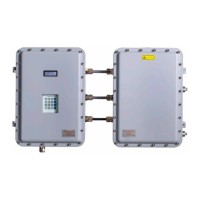
Figure 1. OXY5500 analyzer
Inside the cabinet is the electro-optical module that provides power and other connections to the analyzer. Refer to
Figure 3 for an internal view of the analyzer.
The optional Sample Conditioning System (SCS) contains flow devices for the bypass loop and to control the flow to
the oxygen sensor. A pressure reducing device is also installed to reduce and control the pressure of the sample going
to the oxygen sensor. Depending on the application and/or ambient conditions, the SCS may also contain a heater
and thermostat to maintain the interior of an optional enclosure at a constant temperature. Refer to the Sample
Conditioning System (SCS) Operating Instructions for more information.
2.8.1 Oxygen probe
The oxygen sensor consists of a polymer optical fiber (POF) with a polished distal tip that is coated with a planar
oxygen-sensitive foil. The end of the polymer optical fiber is covered with a high-grade steel tube to protect both the
sensor material and the POF. Refer to Figure 3. Typically, the fiber is coated with an optical isolated sensor material
in order to exclude ambient light from the fiber sensor spot.
2.8.1.1 Schematic drawing for the oxygen probe
Refer to Figure 5 for a schematic of the trace oxygen probe.
Figure 2. Trace oxygen probe schematic
Sensor
SMA

 Loading...


