Smartec S CLD132 Wiring
Endress+Hauser 19
Wiring diagram
C07-CLD132xx-04-06-04-xx-001.eps
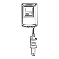
Fig. 17: Terminal assignments of cable glands on Smartec S CLD132
A
1
2
3
4
5
6
Separate version
Plug, Pg 13.5, analog output, binary input
Cable gland for alarm contact, Pg 13.5
Cable gland for power supply, Pg 13.5
Housing ground
Pressure comp. element PCE (Goretex®- filter)
Cable gland for sensor connection, Pg 9
B
1
2
3
4
5
Compact version
Plug, Pg 13.5, analog output, digital input
Cable gland for alarm contact, Pg 13.5
Cable gland for power supply, Pg 13.5
Housing ground
Pressure comp. element PCE (Goretex®- filter)
C07-CLD132xx-04-06-00-de-003.eps
Fig. 18: Electrical connection of Smartec S
A
1
2
3
4
5
6
B
12
3
4
5
 Loading...
