Wiring Smartec S CLD134
26 Endress+Hauser
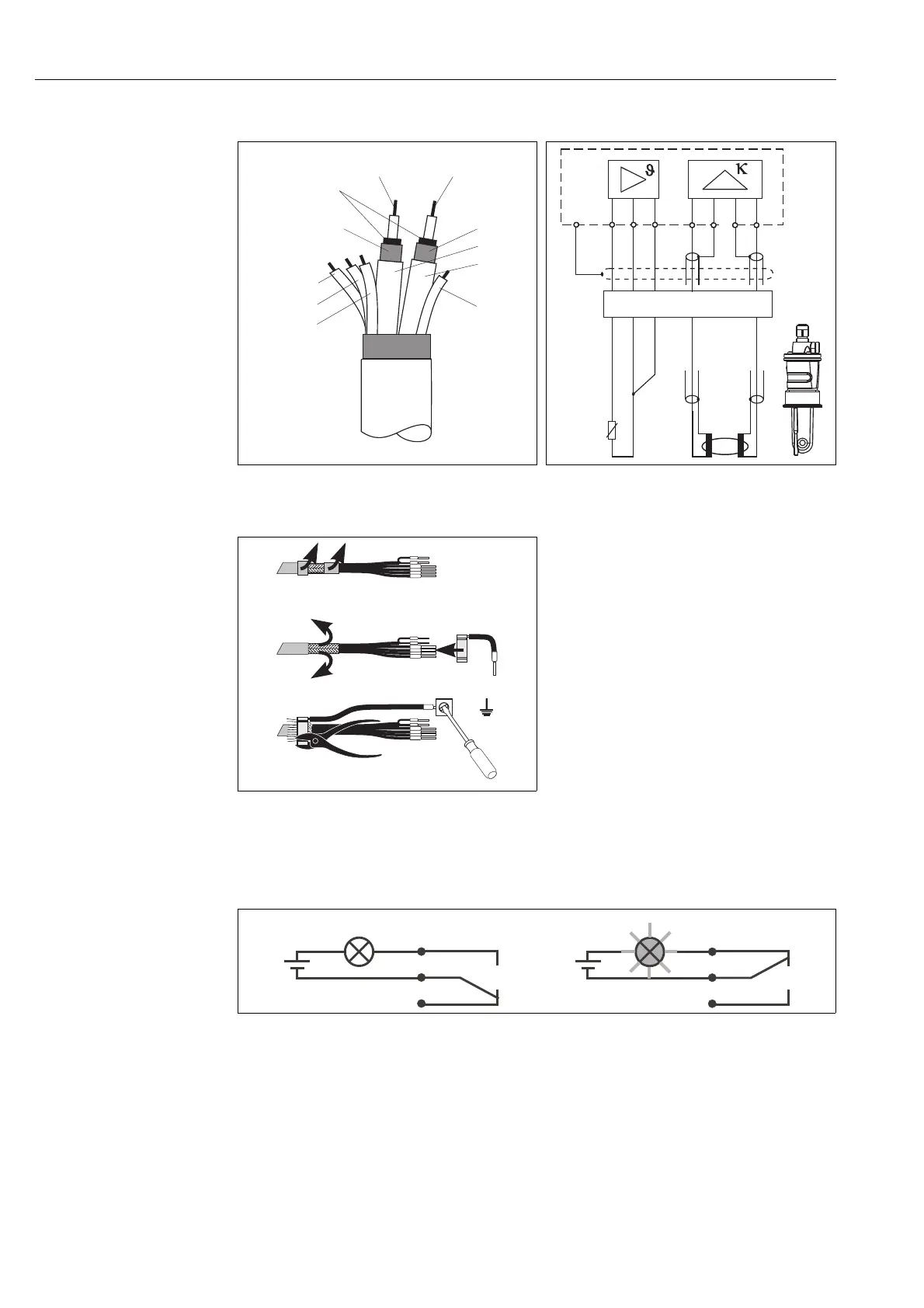
Structure and termination of measuring cable
4.2 Alarm contact
a0005640-en
Fig. 24: Structure of CLK5 measuring cable
a0004906
Fig. 25: Electrical connection of the CLS54 sensor for
the separate version
a0005043
Fig. 26: Screen connection CLK5
Install the ready-made special measuring cable
as shown in the figure:
• Insert the cable through a cable gland into the
wiring compartment.
• Strip approx. 3 cm (1.2 ") of the braided
screen and fold it back over the cable
insulation.
• Push the crimping ring attached to the
supplied screen connection over the prepared
braided screen and pull the ring tight with a
pair of pliers.
• Connect the litz wire to the screen
connection.
• Connect the remaining wires according to the
connection diagram.
• Tighten the cable gland.
C07-CLD132xx-04-06-00-xx-005.eps
Fig. 27: Recommended fail-safe circuit for an alarm contact
A Normal operating state B Alarm state
Normal operating state
• Instrument in operation
• No error message available (Alarm LED off)
È Relay picked up
È Contact 42/43 closed
Alarm state
• Error message available (Alarm LED red)
or
• Instrument defective or voltage-free (Alarm LED
off)
È Relay dropped out
È Contact 41/42 closed
(84) (83)
GN (11)
WH (12)
YE (13)
CLK5
RD
WH
Semiconductor
screen
Screen
(16)
Screen
(15)
BN
(unused)
J
83
11
S
12
16
15
84
CLK5
13
GN
WH
YE
RD
WH
BU
RD
RD
BU
 Loading...


