Smartec S CLD134 Commissioning
Endress+Hauser 33
6 Commissioning
6.1 Function check
#
Warning!
• Check all connections for correctness.
• Make sure that the supply voltage is identical to the voltage indicated on the nameplate!
6.2 Start-up
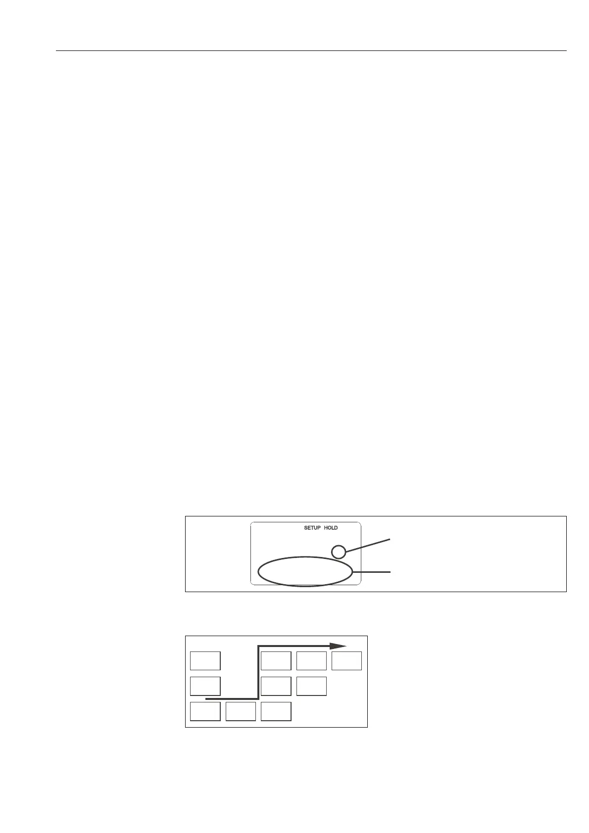
C07-CLD132xx-07-06-00-en-003.eps
Fig. 32: Example for display in setup mode
For a detailed description of the function groups available on the Smartec S CLD134 see the chapter
"Instrument configuration".
Before first start-up, make sure you understand
how to operate the transmitter. You should
make particular reference to chapters 1 (Safety
instructions) and 5 (Operation).
After power-up (connection to power), the
instrument performs a self-test and then enters
the measuring mode.
Calibrate the sensor as described in the chapter
"Calibration".
!
Note!
During first start-up, calibration of the sensor is
absolutely required to enable the measuring
system to perform accurate measurement.
Configure the transmitter as described in the
chapter "Quick setup". The values set by the
user are kept even in the event of a power
failure.
The following function groups are available on
the Smartec S CLD134 (the function groups that
are only available on the version equipped with
the function extension are marked accordingly
in the function descriptions):
Setup mode
• SETUP 1 (A)
• SETUP 2 (B)
•OUTPUT (O)
•ALARM (F)
•CHECK (P)
•RELAY (R)
• ALPHA TABLE (T)
• CONCENTRATION (K)
• SERVICE (S)
• E+H SERVICE (E)
•INTERFACE (I)
• TEMPERATURE COEFFICIENT (D)
•MRS (M)
Calibration mode
• CALIBRATION (C)
s
F3
Err.delay
Function display:
The displayed code indicates
the function position in the
function group.
Additional information
2
C07-CLD132xx-13-06-00-xx-005.eps
Fig. 33: Function coding
Selecting and locating functions is facilitated by
a code displayed for each function in a special
display field Fig. 32.
The structure of this coding is given in Fig. 33.
The first column indicates the function group as
a letter (see group designations). The functions
in the individual groups are counted from the
top to the bottom and from the left to the right.
C C1 C111
C121
C131 C132 C133