Wiring Smartec S CLD134
22 Endress+Hauser
4 Wiring
4.1 Electrical connection
#
Warning!
• The electrical connection must only be carried out by a certified electrician.
• Technical personnel must have read and understood the instructions in this manual and must
adhere to them.
• Ensure that there is no voltage at the power cable before beginning the connection work.
4.1.1 Electrical connection of transmitter
Proceed as follows to connect the Smartec S CLD134:
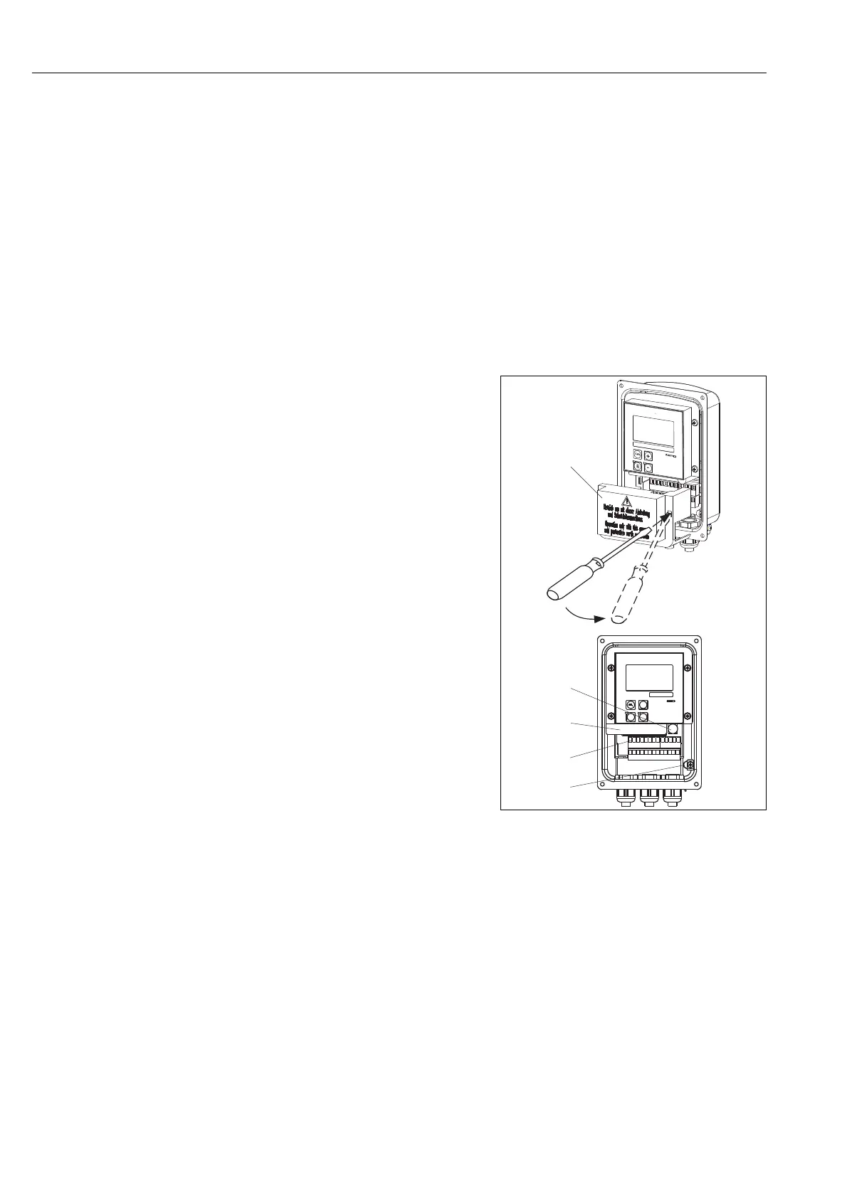
1. Loosen the 4 Phillips screws on the housing
cover and remove the cover.
2.
#
Warning!
Do not remove the cover frame while the
instrument is energized!
Remove the cover frame from the terminal
blocks. To do this, introduce a screwdriver in
the recess (A) according to Fig. 18 and push
the tab inward (B).
3. Thread the cables through the open cable
glands into the housing according to the
terminal assignments in Fig. 19.
4. Connect the power wires according to the
terminal assignments in Fig. 20.
5. Connect the alarm contact according to the
terminal assignments in Fig. 20.
6. Connect the housing ground.
7. Separate version: Connect the sensor
according to the terminal assignments in
Fig. 20.
In the case of the separate version, the
conductivity sensor CLS54 is connected using
the shielded multi-core special cable CLK5.
Preparation instructions are supplied with the
cable. Use junction box VBM (see chapter
"Accessories") to extend the measuring cable.
The maximum cable length if extended using
a junction box is 55 m (180 ft.).
8. Tighten the cable glands firmly.
a0005636
Fig. 18: View of housing with cover removed
1Cover frame
2 Fuse
3 Removeable electronics box
4Terminals
5 Housing ground