Smartec S CLD134 Wiring
Endress+Hauser 23
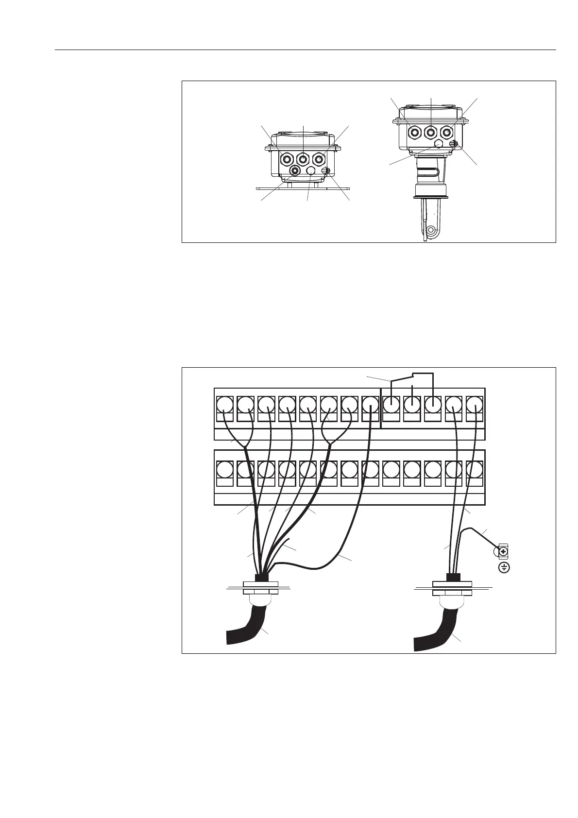
Wiring diagram
a0005439
Fig. 19: Terminal assignments of cable glands on Smartec S CLD134
A
1
2
3
4
5
6
Separate version
Cable gland for analog output, binary input
Cable gland for alarm contact
Cable gland for power supply
Housing ground
Pressure comp. element PCE (Goretex
®
- filter)
Cable gland for sensor connection, M 16x1.5
B
1
2
3
4
5
Compact version
Cable gland for analog output, digital input
Cable gland for alarm contact
Cable gland for power supply
Housing ground
Pressure comp. element PCE (Goretex
®
- filter)
a0005637-en
Fig. 20: Electrical connection of Smartec S CLD134
Pg 13.5
PE
31 32 33 34 85 86 93 94 81 82
15 84 12 13 11 16 83 S 42 43 41 ((
CLK 5
Pg 13.5
GN
YE
WH
GN/YE
BU
BN
Screen
Screen
BN
(unused)
CLK5
with CLS54 sensor
Power supply
Alarm
(contact position: no current)
Coax
WH
Coax
RD
outer
screen
 Loading...


