Wiring Smartec S CLD134
24 Endress+Hauser
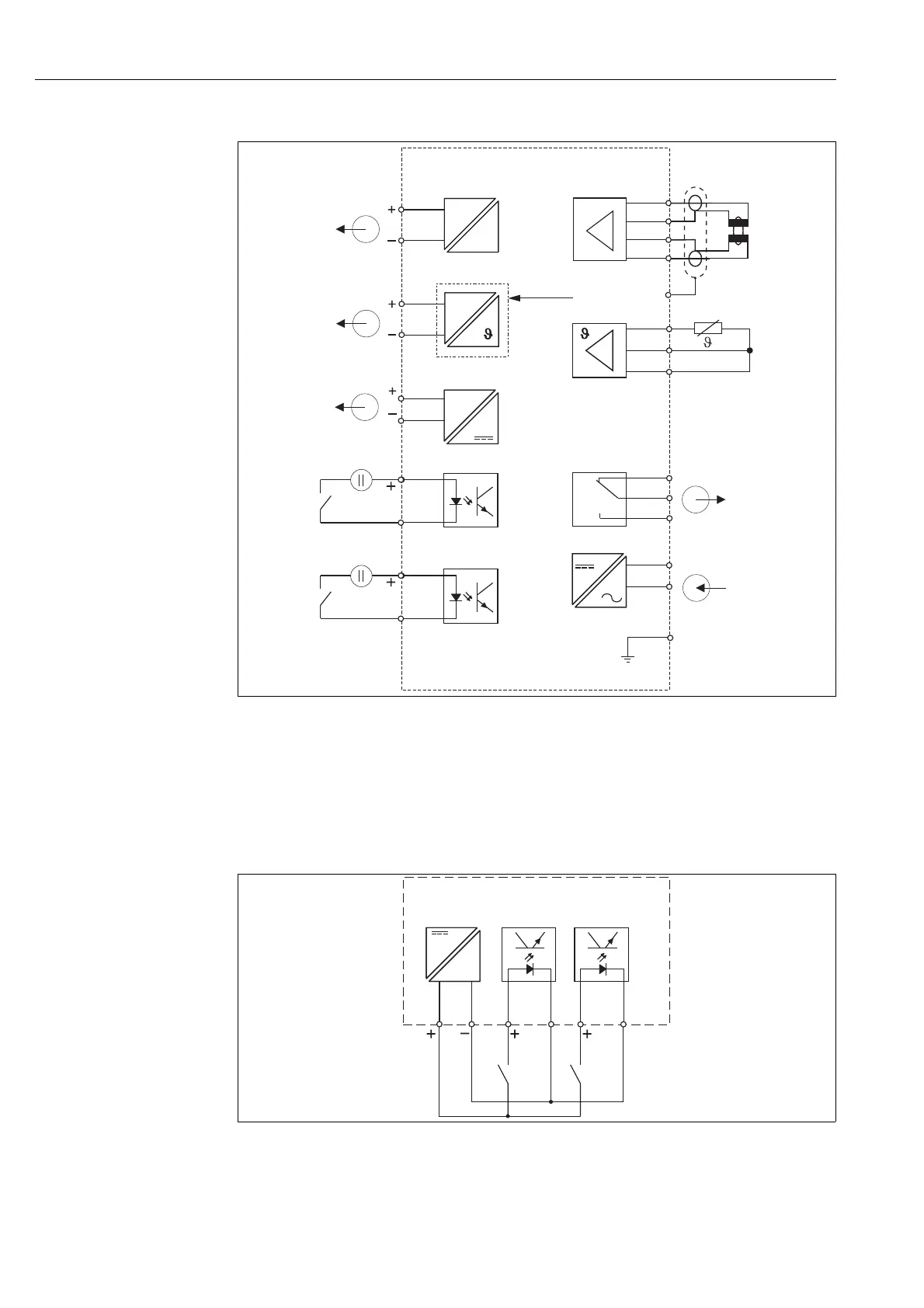
Connection diagram
Connection of binary inputs
a0005639
Fig. 22: Connection of binary inputs when using external contacts
A Auxiliary power output
B Contact inputs D1 and D2
S1 External contacts, not energized
S2 External contacts, not energized
a0004895
Fig. 21: Electrical connection of Smartec S CLD134
A
B
C
D
E
Signal output 1 conductivity
Signal output 2 temperature
Auxiliary power output
Binary input 2 (MRS1+2)
Binary input 1 (hold / MRS 3+4)
F
G
H
I
MRS
Conductivity sensor
Temperature sensor
Alarm (contact position: no current)
Power supply
Remote parameter set switching (measuring range
switching)
15 V
85
10-50 V
81
82
10-50 V
93
94
41
Lf
mA
mA
33
11
S
84
83
15
16
~
–
~
–
32
31
34
12
13
86
42
optional
A
B
C
E
D
F
G
H
I
PE
43
85
S1
D1
15 V
A
B
D2
86 81 82
93
94
S2