Smartec S CLD134 Commissioning
Endress+Hauser 45
C07-CLD132xx-05-06-00-xx-008.eps
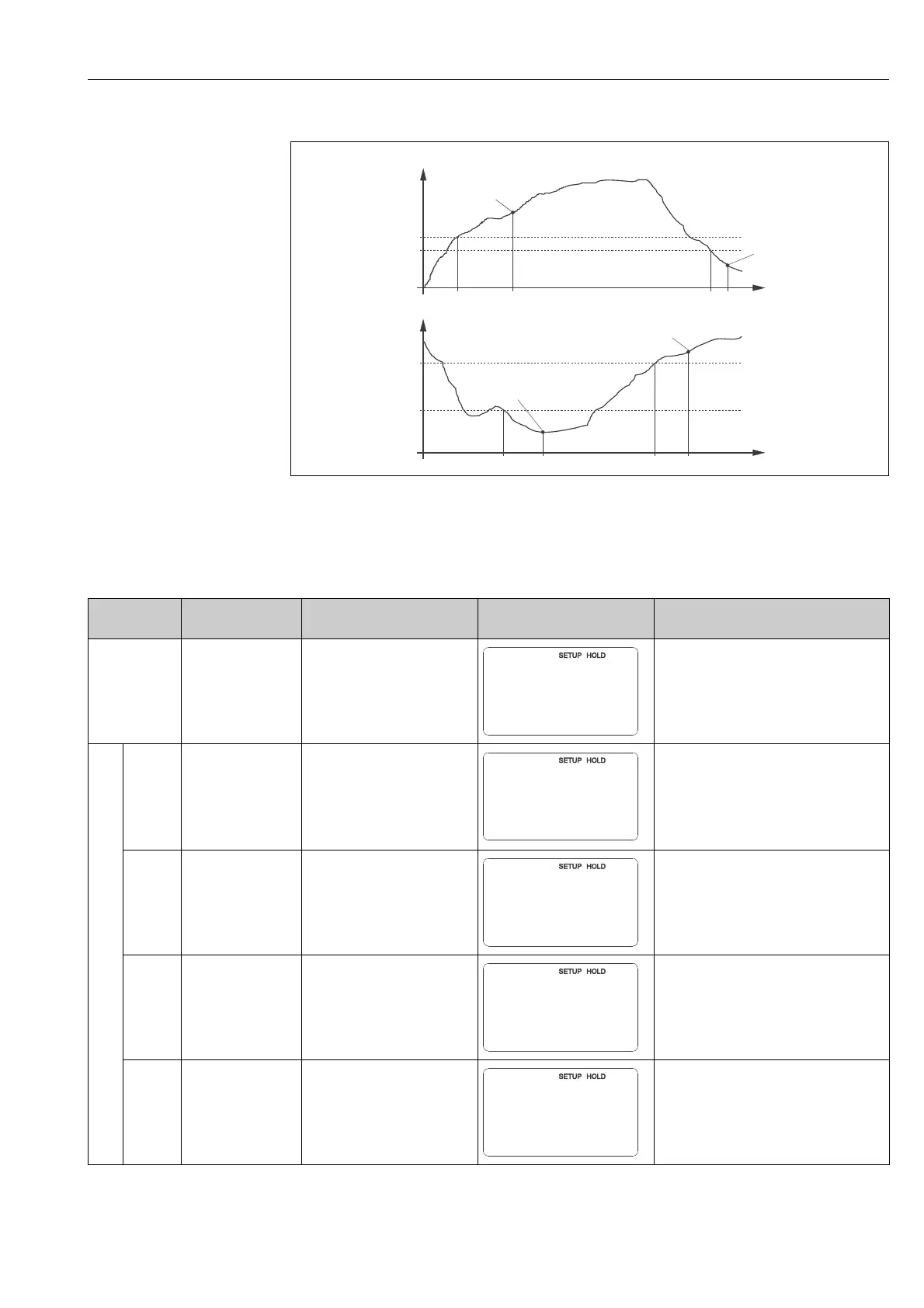
Fig. 38: Relation of switch-on and switch-off points and pickup and dropout delays
A
B
Switch-on point > switch-off point: Max. function
Switch-on point < switch-off point: Min. function
1
2
3
4
Switch-on point
Switch-off point
Contact ON
Contact OFF
A
B
t
1
t
2
t
3
t
4
t
t
1
t
4
t
2
t
3
t
1
2
3
4
2
1
3
4
Coding Field Selection or range
(factory settings bold)
Display Info
R
Function group
RELAY
Settings for relay contacts.
R1 Select function
alarm
limit
al+li = alarm + limit
When “alarm” is selected, the fields R2 ... R5
are irrelevant.
R2
Enter contact
switch-on point
Cond: 2000 mS/cm
Conc: 99.99 %
entire measuring range
Only the operating mode selected in A1
appears.
!
Note!
Never set the switch-on point and the
switch-off point to the same value.
R3
Enter contact
switch-off point
Cond: 2000 mS/cm
Conc: 99.99 %
entire measuring range
The switch-off point entry selects a max
contact (switch-off point < switch-on point) or
a min contact (switch-off point > switch-on
point), thereby implementing a hysteresis
function (see Fig. 32).
R4 Enter pickup delay
0 s
0 ... 2000 s