5 Operation
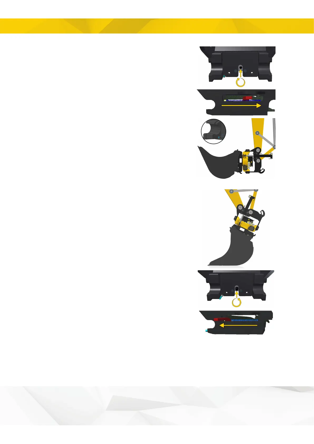
5. Close the quick coupler with a suitable tool.
On models with a screw, turn it clockwise until the locking
bolts are retracted and the indicator rod is in its innermost
position.
On models with a lever, the lock closes automatically
when the adapter axle forces the lock clamp up.
6. Check that the quick coupler lock's lock function has
engaged. In the case of engcon’s other quick couplers,
the blue indicator rod will no longer protrude from the
coupler. Indicator rod location may vary depending on the
tiltrotator model.
5.9.4. Disconnecting the tool, mechanical
lock
1. Place the tool on the ground, with the locking bolts
pointing away from the cab.
2. Open the quick coupler lock with a suitable tool.
On models with a screw, turn it counter-clockwise until
the locking bolts engage and the indicator rod is in its
outermost position.
On models with a lever, use an extension pipe and move
the lever to its end position. The indicator rod will then be
in its outermost position and the lock clamp will keep the
locking bolts open.
In this position the tool is free !
33