7. Product Description CC300 Operator Panel – User Guide
Optionally, an additional DP cable (DisplayPort cable) can be connected to the mainboard
and led out through the cable gland. A digital display can be connected to the DP cable.
7.2.1. Harting Connector
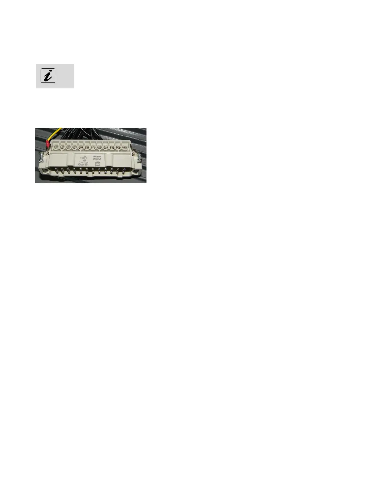
Fig. 18: Harting connector
All outgoing cables of the CC300 operator panel are routed through the cable gland at the rear side of the
cabinet (see also Fig. 17, Pos. 12). Except for the cables for the linear actuator and the grounding cable, all
single wires are combined in the 24-pole Harting connector (Fig. 18). For the pin assignment of the Harting
connector, refer to chapter 10.1.1 “Harting Connector”.
7.2.1.1. Power Supply via the Harting Connector
The power supply of the CC300 operator panel will be provided via pin 7 (24 Volts; cable No. 6) and pin 19
(0 Volts; cable No. 5) of the Harting connector.
7.2.1.2. Control and Signal Lines
The power supply of the linear actuator, the interrupt circuits 1 to 4 (optional: 1 to 6) of the emergency
stop switch and other control lines (power transformer switch-off, Dig In 1) are also routed through the
24-pin Harting connector. For the pin assignment of the Harting connector, refer to chapter 10.1.1
“Harting Connector”.
7.2.2. Connection Cables for the Linear Actuator
The two single cables marked “1” and “2” (see Fig. 17, Pos. 10) will be connected to the linear actuator of
the tilting mechanism.
26 Preliminary Version 0.2