1. Table of Contents CC300 Operator Panel – User Guide
1.1. Table of Figures
Fig. 1: CC300 Operator Panel - Nameplate ..................................................................................................... 14
Fig. 2: Bottom view ......................................................................................................................................... 18
Fig. 3: Right view ............................................................................................................................................. 18
Fig. 4: Front view ............................................................................................................................................. 18
Fig. 5: Rear view .............................................................................................................................................. 18
Fig. 6: Left view ............................................................................................................................................... 18
Fig. 7: Top view ............................................................................................................................................... 18
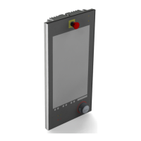
Fig. 8: Front view of the CC300 operator panel ............................................................................................. 19
Fig. 9: On/Off button....................................................................................................................................... 20
Fig. 10: RFID-read/write zone ......................................................................................................................... 20
Fig. 11: Emergency stop switch ...................................................................................................................... 21
Fig. 12: Buttons for tilting out and in the CC300 operator panel ................................................................... 21
Fig. 13: Traversing buttons below the touch display ...................................................................................... 23
Fig. 14: Markings for laterally mounted USB 2.0 ports .................................................................................. 23
Fig. 15: Permissive button and program interrupt button ............................................................................. 23
Fig. 16: Rotary/push button with illumination and display ............................................................................ 24
Fig. 17: Rear side of the CC300 operator panel .............................................................................................. 25
Fig. 18: Harting connector .............................................................................................................................. 26
Fig. 19: Grounding cable ................................................................................................................................. 27
Fig. 20: LAN cables .......................................................................................................................................... 27
Fig. 21: Right side of the CC300 operator panel ............................................................................................. 28
Fig. 22: Left side of the CC300 operator panel ............................................................................................... 28
Fig. 23: USB ports ............................................................................................................................................ 29
Fig. 24: Top view of the CC300 operator panel .............................................................................................. 30
Fig. 25: Bottom view of the CC300 operator panel ........................................................................................ 30
Fig. 26: Carefully open the CC300 a few inches.............................................................................................. 32
Fig. 27: Unlocking and removing the auxiliary switch block ........................................................................... 32
Fig. 28: CC300 operator panel, fully opened .................................................................................................. 33
Fig. 29: Removong the lithium battery from the battery holder ................................................................... 35
Fig. 30: Dimensioned view of the CC300 glass front (print side - reversed image) ....................................... 42
Fig. 31: Dimensioned rear and side view of the CC300 operator panel ......................................................... 43
Preliminary Version 0.2 5