7. Product Description CC300 Operator Panel – User Guide
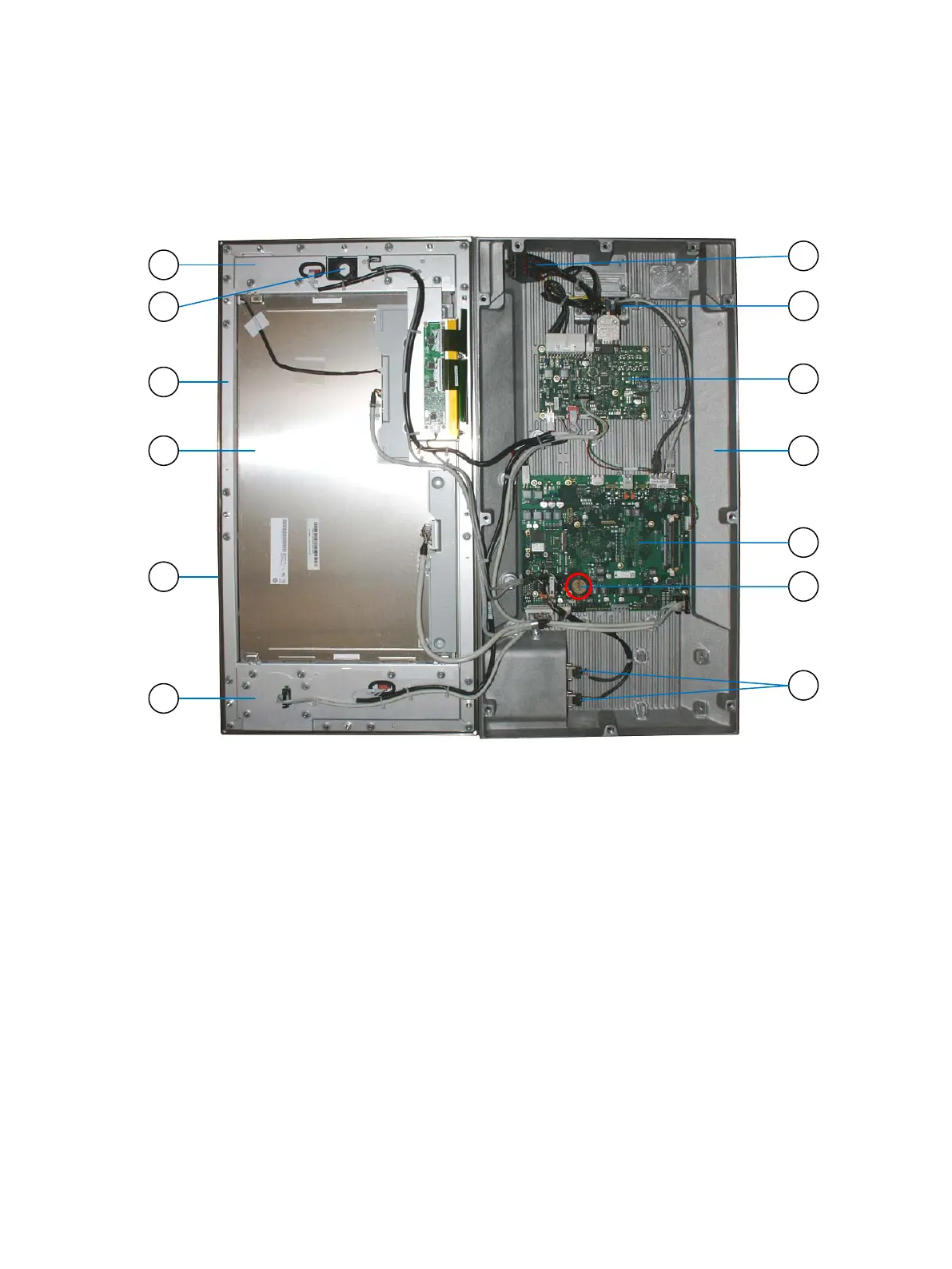
5. Now the CC300 operator panel can be folded apart carefully.
Fig. 28: CC300 operator panel, fully opened
Legend for Fig. 27:
1 Circuit area above the display
2 Mounting of the auxiliary switch block
(of the emergency stop switch)
3 Front plate with aluminum frame
4 Display with capacitive touch
5 Surrounding seal
6 Circuit area below the display
7 2x USB ports (externally accessible)
8 Position of the lithium battery on the CPU
board
9 CPU board (mainboard)
10 Aluminum rear cover
11 I/O board
12 Mounting and opening of the cable gland
13 Auxiliary switch block (detached)
Preliminary Version 0.2 33