22
Initial Installation
QUALIFIED INSTALLERS ONLY
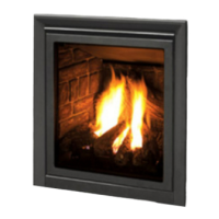
Vent teRmination FRaming:
Minimum venting is shown in gure 29.
the framing height to the center of the
thimble is 62”. Minimum venting must
include a 24” vertical section and a 90
degree elbow which is then terminated
horizontally.
For a vertical termination please
follow the vent pipe manufacturer’s
installation instructions for vertical
vent termination framing.
A minimum of 1” (25 mm) clearance
on all sides of the vertical vent pipe
must be maintained.
For every 12” of horizontal run
there must be a 1/4” of rise.
1” of clearance between framing
and venting must be maintained
at all times. 2” above the venting
and 3” above an elbow.
Please see vent cap clearance
in page 31. Also refer to local
building and re codes.
Figure 29: Minimum Horizontal Venting
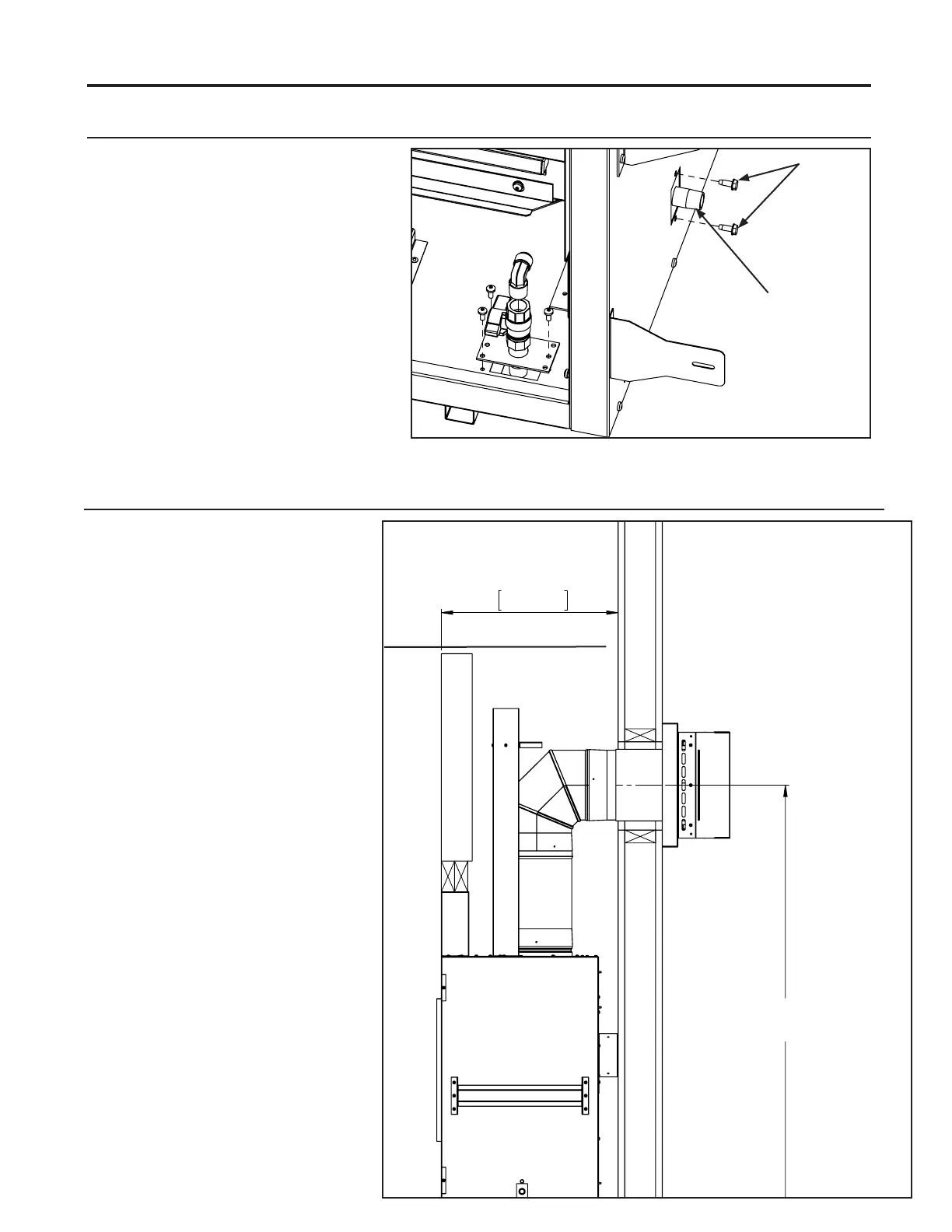
aLteRnate gas inLet Location:
The gas inlet location can be moved to the
bottom of the cabinet if needed. This may
be needed for certain installations. First
remove the two screws on the left side
of the unit, see Figure 28. The gas inlet
assembly will now be loose in the cabinet.
Disconnect the gas line coming from the
gas valve, the straight tting the gas line
was connected too will be reaplaced by a
elbow supplied in the manual bag. Thread
the elbow into the shut o valve, use gas
sealant on threads. Mount the assembly
to bottom of the rebox as shown, screws
come installed in rebox. Reconnect the
gas line to elbow.
Remove
Figure 28: Alternate Gas Inlet Location
Move
20"
509mm
62"
[1575mm]
*Do not use two
12” vent sections
or this dimension
will not work.
Use one 24”
section.