32
Initial Installation
QUALIFIED INSTALLERS ONLY
J 12 in (30 cm) 9 in (23 cm) Clearance to non-mechanical air supply inlet to building, or
the combustion air inlet to any other appliance.
K 6 ft (1.83 m) 3 ft (91 cm) above if within 10
ft (3 m) horizontally
Clearance to mechanical air supply inlet.
L 7 ft (2.13 m
)t
7 ft (2.13 m)
*t
Clearance above paved sidewalk or paved driveway located
on public property.
M 12 in / 30 cm
+
12 in / 30 cm*
+
Clearance under verandah, porch, deck, or balcony.
N 12 in (30 cm)* Clearance horizontally to any surface (such as an exterior
wall) for vertical terminations.
O 12 in (30 cm) Clearance above roof line for vertical terminations.
1
In accordance with the current CSA B149.1, Natural Gas and Propane Installation Code.
2
In accordance with the current ANSI Z223.1 NFPA 54, National Fuel Gas Code.
* These numbers are only estimates.
t
A vent shall not terminate directly above a side walk or paved driveway that is located between two single family dwellings
and it serves both dwellings.
+
Permitted only if verandah, porch, deck, or balcony is fully open on a minimum of two sides beneath the oor.
Clearances are in accordance with local installation codes and the requirements of the gas supplier.
NOTE: Venting terminals shall not be recessed into walls or siding.
Venting cLeaRances:
A 1” (25 mm) clearance to combustibles must be maintained around any vertical vent pipe. Around
a horizontal vent pipe, the clearance to combustibles should be 2” (51 mm) above and 1” (25 mm)
on the sides and bottom. When combustible materials are directly above a 90° elbow, 3” (76 mm) of
clearance is necessary.
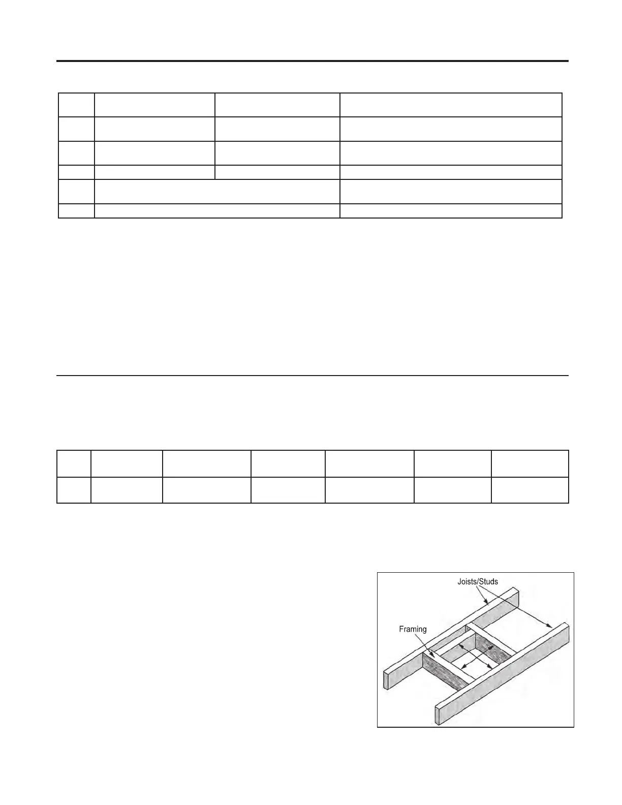
Table 4. Vent Pipe Minimum Clearances
Vertical Pipe to
the Side Walls
Horizontal Pipe to
the Sides & Bottom
Above an Elbow
Above the Unit
Above an Elbow
Not Above the Unit
Above Horizontal
Vent Pipe
Wall Frame 8”
(203mm) or less
Hard
Pipe
1”
(25.4 mm)
1”
(25.4 mm)
3”
(76.2 mm)
3”
(76.2 mm)
2”
(51 mm)
Thimble
Specic
See certied thimbles in venting section and frame accordingly (see Figure 40) will assure the proper
support and spacing for the vent pipe as it passes through the wall. Installations in Canada require that a
wall thimble be used for passing through walls and ceilings. All sealing and vapour barriers must comply
with local building codes.
The conguration of the venting pipes depends on the locations
of walls, ceilings, and studs. However, the pipes cannot be of
arbitrary length and arrangement. Because the length of the
vertical and horizontal sections dramatically aects the burning
eciency of the replace, certain guidelines have been set in
InItIal InstallatIon - allowaBle co-axIal Vent confIguratIons.
Venting terminals can not be recessed into a wall or siding.
WARNING: This gas appliance must not be connected
to a chimney ue serving a separate solid-burning
appliances.
Figure 40. Vent Framing For Wall or Ceiling