37
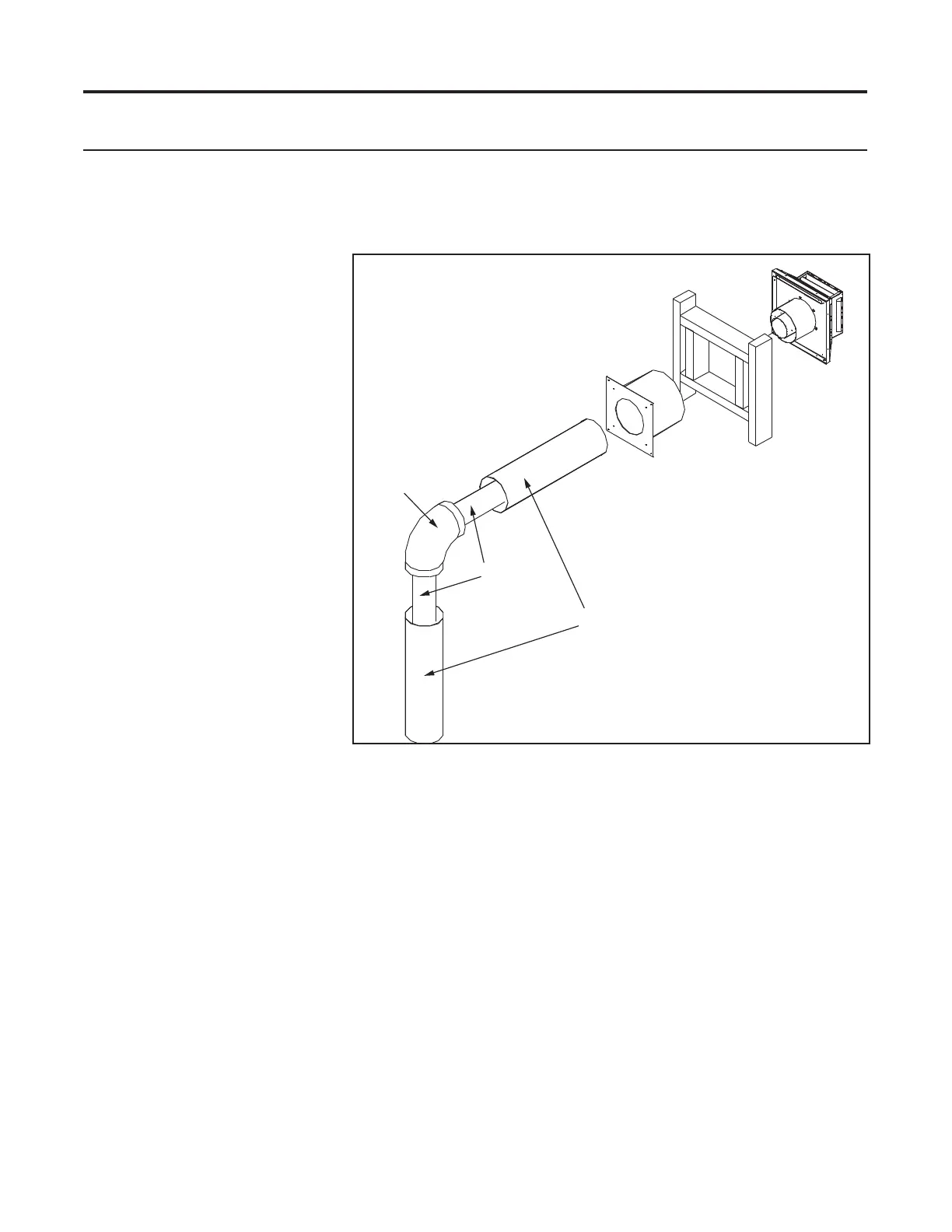
Wall Framing
Horizontal
Termination
Wall Thimble
Fire Stop
Exhaust Pipe
Combustion Air
Outer Pipe
Elbow
Initial Installation
QUALIFIED INSTALLERS ONLY
hoRizontaL teRmination:
1. A MINIMUM OF 24” [610mm] VERTICAL RISE PLUS AN ELBOW IS REQUIRED
WHEN HORIZONTALLY TERMINATING WITH AN APPROVED VENT CAP.
2. Horizontal pipes must not
be level. For every 12” (305
mm) of horizontal travel
(away from the stove),
there should be at least ¼”
(6.4 mm) of vertical rise.
Never allow the vent to run
downward, as this could
cause high temperatures or
even present the possibility
of a re.
3. The exterior of the horizontal
vent termination must not be
blocked or obstructed.
4. If the vent termination is not
being attached to wood, the
four wood screws provided
should be replaced with material
appropriate fasteners.
5. For buildings with vinyl siding,
a vinyl stando should be
installed between the vent cap
and the exterior wall. Attach
the vinyl siding stando to the
horizontal termination. Note that the termination bolts onto the at portion of the stando, providing
an air space between the wall and the vent termination. The air gap prevents excessive heat from
possibly melting the vinyl siding.
6. Horizontal pipes must be supported every 3’ (914 mm). Plumber’s all round strap will suce.
7. When running horizontal pipe, clearances to combustibles must be maintained 1 inch (25 mm) sides,
1 inch (25 mm) bottom, and 2” (51 mm) top.
Step 1. Set the replace in the desired location. Check to determine if wall studs will be in the way when
the venting system is attached. If this is the case, the location of the replace may have to be
adjusted or the venting may have to be oset.
Step 2. Direct vent pipe sections are designed with special twist-lock connections. Dry t the desired
combination of pipe and elbows to the appliance adaptor.
Step 3. With the pipe in the correct position and attached to the replace, mark the wall for a hole as
directed by specied wall thimble dimensions. Cut and frame the hole in the exterior wall where
the vent will be terminated. If the wall being penetrated is made of a non-combustible material
(i.e. masonry or concrete) a 8 1/2” (21.6 cm) hole is acceptable.
Figure 45. Horizontal Vent Termination