EPSON Stylus PHOTO 2100/2200 Revision B
DISASSEMBLY AND ASSEMBLY Disassembly 130
4.2.2.4 Removing the PSB/PSE Board
1. Disconnect the Connector Cable from CN15 of the Main Board.
(Refer to Steps 1 and 2 in 4.2.2.3.)
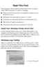
2. Remove the four screws 6) C.B.S 3
×6 (9±1kgf.cm) and two screws 8) C.B.P 3×6
(6±1kgf.cm) that secure the PSB/PSE Board, and remove the PSB/PSE Board
from the Board Unit.
Figure 4-19. Screws That Secure the PSB/PSE Board
A D J U S T M E N T
R E Q U I R E D
" When changing the Main Board, the following part change and
adjustments are necessary. Perform the adjustments in the
following order.
Parts to be changed
• Waste Ink Pads
Adjustment items
1. EEPROM data
2. EEPROM initialization
3. USB ID input
4. IEEE-1394 ID input
5. Head ID input
6. Bi-D adjustment
7. Pixel Shift Adjustment
8. PF adjustment
9. PW sensor mounting position adjustment
10. CR Motor drive torque dispersion measurement
(maximum correction value input)
" Refer to "Chapter 5 Adjustment" for the adjustment
procedures.
" When data can be read from the old Board, adjustments and
Waste Ink Pad changing are not necessary.
" Fit the screws 8) C.B.P 3×6 in the order shown in Figure 4-19.
" Always fit the Protective Sheet under the PSB/PSE Board after
matching the two screw holes with those of the Board Unit.
Refer to Figure 4-20, "Fitting the Protective Sheet".
Figure 4-20. Fitting the Protective Sheet
C.B.S 3×6
PSB/PSE
Board
C.B.P 3×6
1
2
3
4
Protective Sheet
Screw holes

 Loading...