EPSON Stylus PHOTO 2100/2200 Revision B
DISASSEMBLY AND ASSEMBLY Disassembly 139
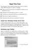
" Reinstall the Left and Right LD Roller Units so that the grooves
on the rear side of the LD Roller Units engage the rail of the ASF
Frame.
Refer to Figure 4-38, "Reinstalling the LD Roller Units".
" When reinstalling the Left LD Roller Unit to the Edge Guide
bottom side of the Hopper, engage the rib of the Left LD Roller
Unit with the groove of the Edger Guide as seen from the ASF
Unit front.
Refer to Figure 4-38, "Reinstalling the LD Roller Units".
Figure 4-38. Reinstalling the LD Roller Units
"
When reinstalling the Left and Right Hopper Cams, place them
so that the markings of the Cams face rightward as viewed from
the ASF Unit front.
Refer to Figure 4-39, "Marking Position of the Hopper Cam".
Figure 4-39. Marking Position of the Hopper Cam
Rib
Groove
Edge Guide
Hopper Cam
Marking
" When reinstalling the ASF Sensor Wheel, Left and Right Hopper
Cams and LD Roller, refer to Figure 4-40 and face the home
position (notch) of the ASF Sensor Wheel, the cam diameters of
the Left and Right Hopper Cams and the plane surface of the LD
Roller face the same direction.
Figure 4-40. Phase Matching
A D J U S T M E N T
R E Q U I R E D
" When changing the following parts for new ones, always apply
grease G-26 to the specified places.
• ASF Frame: Refer to Chapter 6, Figure 6-15, "Lubrication
Point 17".
• Hopper : Refer to Chapter 6, Figure 6-15, "Lubrication
Point 17".
Notch

 Loading...