EPSON Stylus PHOTO 2100/2200 Revision B
DISASSEMBLY AND ASSEMBLY Disassembly 184
4.2.18.2 Removing the Cutter Motor
1. Remove the Cutter Housing. (Refer to Steps 1 and 2 in 4.2.18.1.)
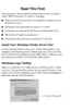
2. Disconnect the Connector Cable (CN2) from the Driver Board and release it from
the Harness Clamp.
Figure 4-143. Disconnecting the Connector
3. Remove the two screws 16) C.P 2.5×3 (4±0.5kgf.cm) that secure the Cutter Motor,
and while pulling and stretching the Timing Belt, remove the Pinion Gear of the
Cutter Motor and remove the Cutter Motor from the Cutter Unit.
Figure 4-144. Screws That Secure the Cutter Motor
Harness Clamp
Connector
Driver Board
Cutter Motor
C.P 2.5×3
Pinion Gear
Timing Belt

 Loading...