Setup & Operation 4. End Effectors
48 S5 Rev.5
If the load or moment of inertia exceed the ratings or if the load becomes eccentric, follow
the steps in the Setup & Operation 4.3.1 WEIGHT Setting and 4.3.2 INERTIA Setting, to
set parameters.
Setting parameters makes the operation of the Manipulator optimal, reduces vibration to
shorten the operating time, and improves the capacity for larger loads. In addition, it
reduces persistent vibration produced when the moment of inertia of the end effector and
work piece is bigger.
The allowable weight for S5 series Manipulators is up to 5 kg (7 kg*). However, the
moment and the moment of inertia should also be considered due to limitations for these
factors.
If force is applied to the Manipulator instead of the weight, force on the Arms #4, #5, and
#6 should be within the values shown in the table “Allowable Moment and Moment of
Inertia for S5 series Manipulators”.
* When the load of the Manipulator is more than 5 kg and less than or equal to 7 kg,
refer to the section Setup & Operation 4.3.1 WEIGHT Setting - “Restriction on
payload exceeding 5 kg (more than 5 kg and less than or equal to 7 kg)”.
Allowable Moment and Moment of Inertia for S5 series Manipulators
Arm Allowable Moment N·m (kgf·m)
GD
/4 Allowable Moment of Inertia (kg·m
)
#4 12 (1.22) 0.3
#5 12 (1.22)
0.3
#6 7 (0.71) 0.1
*1 Gravitational unit
*2 The allowable moment and allowable moment of inertia of Arm #5 are calculated by
the distance from the Arm #5 rotation center (a + 80 mm). (Refer to the figure in the
“Critical Location of the Load on S5 series Manipulators”).
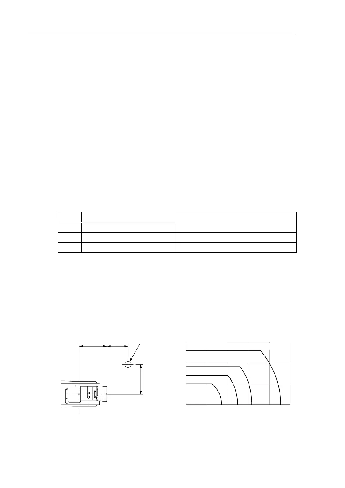
The following figure shows the critical location of the load on the S5 series Manipulators.
Critical Location of the Load on S5 series Manipulators
Position of
Load
’s Center
of Gravity
a: Distance from the Flange
b: Distance from the Arm #6 Rotation Center

 Loading...


