EasyManuals Logo

Epson RC700 Series Maintenance Manual

Epson RC700 Series
90 pages
To Next Page IconTo Next Page
To Previous Page IconTo Previous Page
Page #62 background imageLoading...
Page #62 background image
Maintenance 8. Maintenance Parts Replacement Procedures
48 RC700 Series Maintenance Rev.3
Fan
2
Installation
(RC700
-A,
RC700DU-A)
(1)
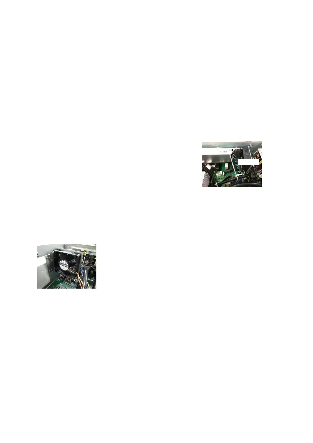
Fix the new fan to the fan fixing plate.
(Mounting screw ×2)
At this point, tighten the screws diagonally. Be careful of the mounting
direction.
(2)
Mount the
regenerative resistance to the rear plate. (Mounting screw ×2)
Be careful of the mounting direction.
(3)
Mount the rear plate to the body.
(Mounting screw ×5)
(4)
Connect the regenerative module connector to the DMB.
(5)
Connect the
regenerative module connector to the DPB.
(6)
Connect the fan extension connector.
(7)
Bind the
15 V power supply cable and fan cable.
by the
cable tie
(AB150).
Leave 110 mm from the end of the cable tie in order not
to tighten the cables too
much.
Cut the excess part of the tie.
110 mm
(8)
Mount the Top Panel. (Mounting screw
×6)
(9)
Connect the power plug
. Turn ON the Controller and make sure that the
Controller
starts properly without any vibration or abnormal noise.
* Pay attention to the right and wrong sides of the fan when installing it.

Table of Contents

Other manuals for Epson RC700 Series

Questions and Answers:

Question and Answer IconNeed help?

Do you have a question about the Epson RC700 Series and is the answer not in the manual?

Epson RC700 Series Specifications

General IconGeneral
ModelRC700 series
CategoryController
Programming LanguageSPEL+
Safety StandardISO 10218-1
TypeRobot Controller
Communication InterfaceEthernet, RS-232, USB
Operating Temperature0°C to 45°C (32°F to 113°F)
Humidity20% to 80% (non-condensing)
Number of controllable robots4

Related product manuals