EasyManuals Logo

Epson RC700 Series Maintenance Manual

Epson RC700 Series
90 pages
To Next Page IconTo Next Page
To Previous Page IconTo Previous Page
Page #74 background imageLoading...
Page #74 background image
Maintenance 8. Maintenance Parts Replacement Procedures
60 RC700 Series Maintenance Rev.3
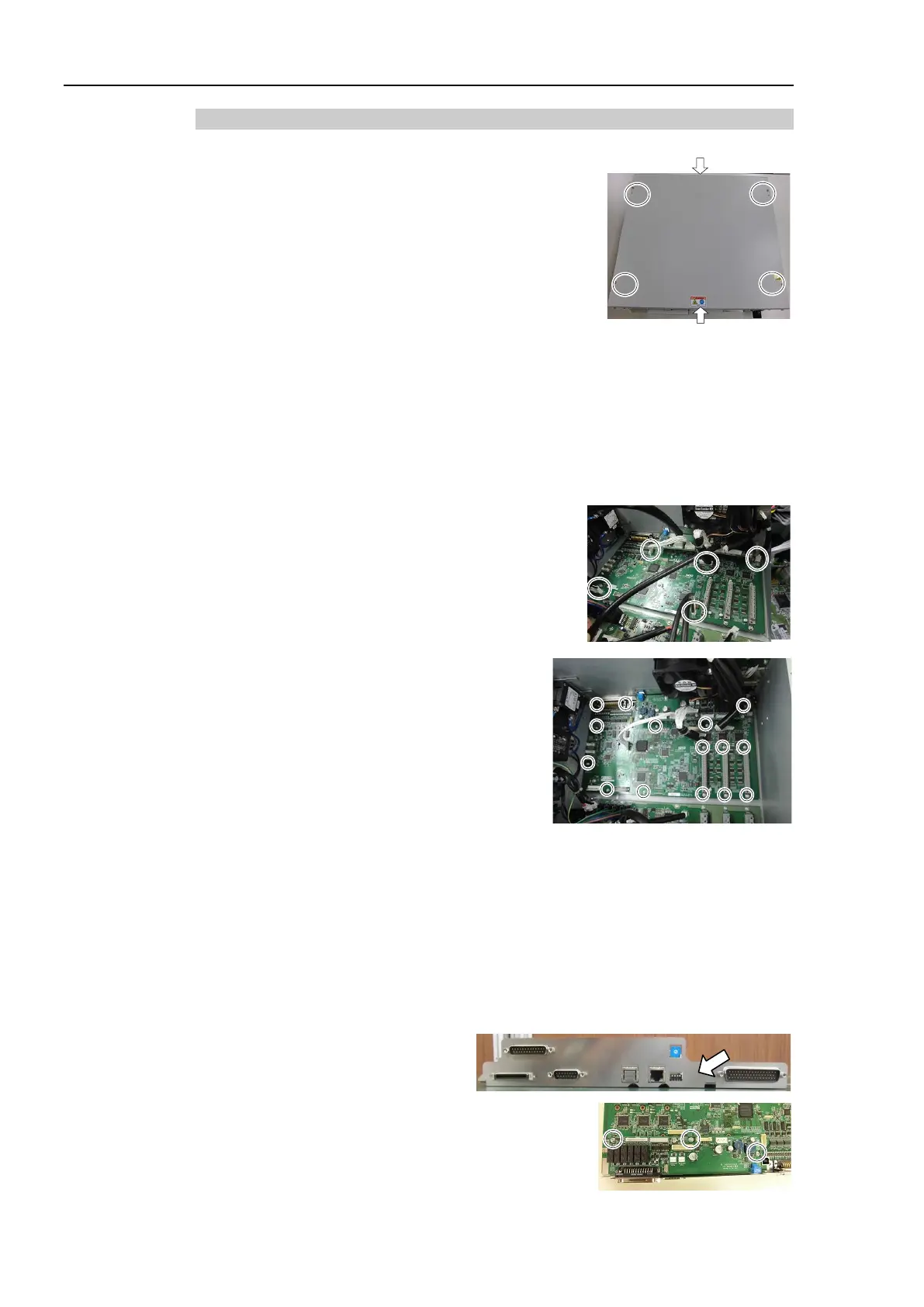
8.6.2 DMB for Drive Unit
DMB
R
emoval
(1)
Turn OFF the
Drive Unit.
(2)
Remove the power plug.
(3)
Remove
the Top Panel. (Mounting screw ×6)
(4)
Remove the cables connected to the following
connectors.
M/C Signal Connector EMERGENCY Connector
R-I/O Connector DU OUT Connector
DU IN Connector I/O Connector
(5)
Remove the MDBs.
Refer to 8.5 MDB.
(6)
Remove
the five connectors from the DMB.
(7)
R
emove the DMB mounting screws (×15).
(8)
Remove the
fan.
Refer to 8.2 Fan.
(9)
Remove the DMB from the chassis.
At this point, be careful not to touch the chassis and other parts.
(10)
Remove the plate fixing the connectors on the front side from the DMB and the DMB
-
SUB boards.
(11)
Remove the DMB
-SUB board from the DMB.
(Mounting screw × 3)

Table of Contents

Other manuals for Epson RC700 Series

Questions and Answers:

Question and Answer IconNeed help?

Do you have a question about the Epson RC700 Series and is the answer not in the manual?

Epson RC700 Series Specifications

General IconGeneral
ModelRC700 series
CategoryController
Programming LanguageSPEL+
Safety StandardISO 10218-1
TypeRobot Controller
Communication InterfaceEthernet, RS-232, USB
Operating Temperature0°C to 45°C (32°F to 113°F)
Humidity20% to 80% (non-condensing)
Number of controllable robots4

Related product manuals