Maintenance 8. Maintenance Parts Replacement Procedures
56 RC700 Series Maintenance Rev.3
8.6 DMB
8.6.1 DMB for Control Unit
emoval
Control Unit.
the power plug.
the Top Panel. (Mounting screw ×6)
cables connected to the following connectors.
M/C Signal Connector EMERGENCY Connector
TP Connector USB Connector
USB Memory Ethernet Connector
I/O Connector RS-232C Connector
R-I/O Connector DU OUT Connector
MDBs.
Refer to 8.5 MDB.
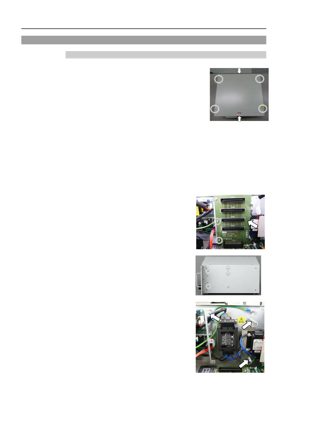
-OPTION board.
(Mounting screw ×3)
screws on the side of the chassis.
Remove the fixing plate of the DMB
-OPTION
board.

 Loading...


