EasyManuals Logo

Epson RC700 Series Maintenance Manual

Epson RC700 Series
90 pages
To Next Page IconTo Next Page
To Previous Page IconTo Previous Page
Page #61 background imageLoading...
Page #61 background image
Maintenance 8. Maintenance Parts Replacement Procedures
RC700 Series Maintenance Rev.3 47
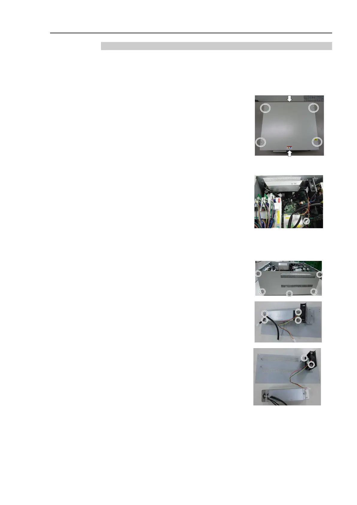
8.2.2 Fan 2 (RC700-A, RC700DU-A)
The fan 2 is installed only in RC700-A and RC700DU-A.
Fan
2
removal
(RC700
-A,
RC700DU
-A)
(1)
Turn OFF the Controller.
(2)
Disconnect the power plug.
(3)
Remove the Top Cover. (Mounting screw
×6)
(4)
Remove the cable tie binding the
15 V power supply cable and fan cable.
(5)
Remove the fan extension connector.
(6)
Remove the regenerative module connector from the DMB.
(7)
Remove the regenerative module connector from the DPB.
(8)
Remove the rear plate from the body.
(Mounting screw
×5)
(9)
Remove the regenerative resistance from the rear
plate.
(Mounting screw
×4)
(
10)
Remove the fan from the fan fixing plate.
(Mounting screw
×2)

Table of Contents

Other manuals for Epson RC700 Series

Questions and Answers:

Question and Answer IconNeed help?

Do you have a question about the Epson RC700 Series and is the answer not in the manual?

Epson RC700 Series Specifications

General IconGeneral
ModelRC700 series
CategoryController
Programming LanguageSPEL+
Safety StandardISO 10218-1
TypeRobot Controller
Communication InterfaceEthernet, RS-232, USB
Operating Temperature0°C to 45°C (32°F to 113°F)
Humidity20% to 80% (non-condensing)
Number of controllable robots4

Related product manuals