Maintenance 7. Option Parts Replacement Procedures
38 RC700 Series Maintenance Rev.3
After connecting the power plug, turn ON the Controller and check it works normally
without
vibration and abnormal sound.
7.2 EUROMAP67 Board
For the detail of the board, refer to the RC700 Series manual.
(1) Turn OFF the Controller.
(2) Disconnect the power plug.
(3) Remove the Top Panel. (Mounting screw ×6)
(4) Insert the EUROMAP67 board into either slots 1, 2 or 3.
(Slot 4 cannot be used.)
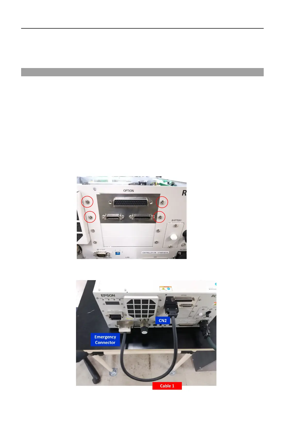
(5) Use four screws to fix the EUROMAP67 board in place.
First, temporarily fasten the four screws in place. Next, fully tighten screws located
diagonally opposite each other.
Take care not to damage the thread holes when doing so.
(6) Connect “Cable1 CN2”.
Use a cross-point screwdriver to fasten the connector (CN2).
(7) Refer to the following to connect CN3 to the emergency stop switch (emergency stop,

 Loading...


