SC-S30600 Series Revision B
DISASSEMBLY & ASSEMBLY Disassembly and Assembly Procedure 121
Confidential
3.4.5.3 Print Head
1. Unlock the CR Unit. (p82)
2. Remove the Left Rear Cover. (p94)
3. Remove the Left Upper Cover. (p95)
4. Remove the CR Cover. (p119)
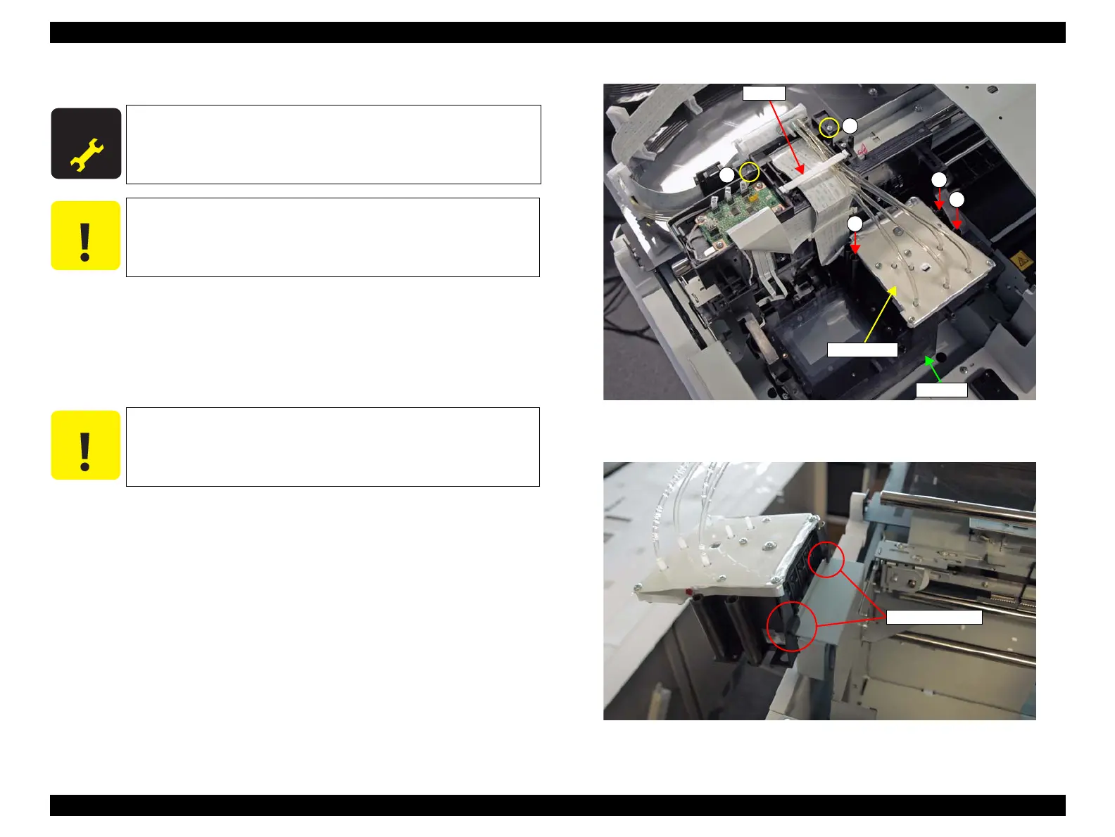
5. Remove the three screws that secure the Damper Kit
A) Silver M3x10: 3 pcs
6. Remove the FFC clamp.
7. Remove the two screws that secure the Ink Path Holder Assy.
B) Silver M3x10: 2 pcs
8. Lift the Damper Kit to remove it from the CR Unit.
Figure 3-66. Removing the Damper Kit
9. Attach the hooks of the Damper Kit to the frame as shown.
Figure 3-67. Temporarily Placing the Damper Kit
A D J U S T M E N T
R E Q U I R E D
When replacing/removing this part, refer to “4.1.2 Adjustment
Items and the Order by Repaired Part” (p200) and make sure to
perform the specified operations including required adjustment.
Be careful not to touch the nozzle surface of the Print Head.
Be sure to move the CR Unit to the left end before performing the
following step. Performing the following step with the CR Unit
located on the platen or the Pump Cap Unit may damage the Print
Head.
Damper Kit
CR Unit
A
Clamp
A
A
B
B
 Loading...