SC-S30600 Series Revision B
DISASSEMBLY & ASSEMBLY Disassembly and Assembly Procedure 187
Confidential
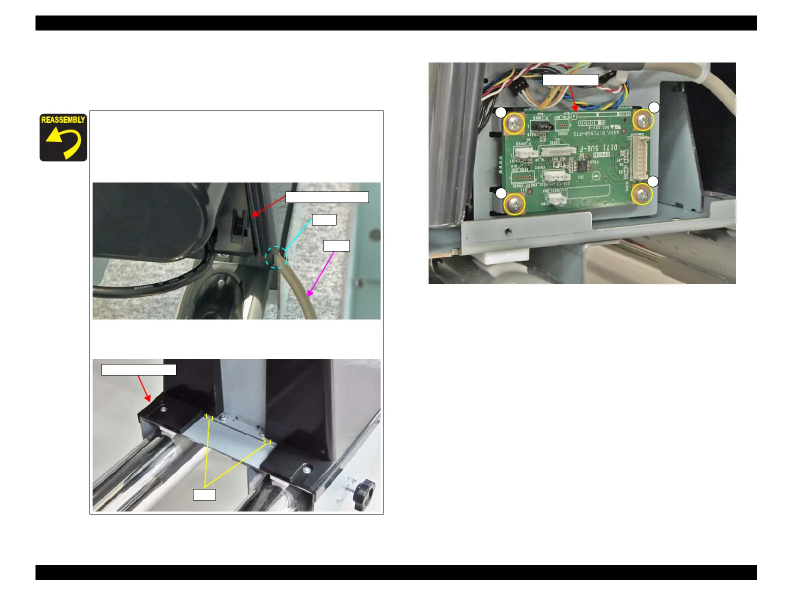
7. Disconnect all cables from the connectors on the Sub-F Board.
8. Remove the four screws, and remove the Sub-F Board.
C)Silver M3x8 S-tite screw: 4 pcs
Figure 3-154. Removing the Sub-F Board
When installing the Sub-F Board, make sure to attach it in the
correct orientation as shown in Figure3-154.
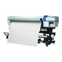
Pull out the cable through the hole on the Right Reel Side
Cover taking care not to let the cable get caught between the
frames.
Insert the two tabs of the Right Reel Cover into the two
positioning holes on the frame.
Hole
Right Reel Side Cover
Cable
 Loading...