Maintenance 4. Cable
G6 Rev.21 111
Remove the arm caps and side covers on Arm #1.
For details, refer to Maintenance: 3.3 Arm #1 Cover.
Remove the arm top cover.
For details, refer to Maintenance: 3.1 Arm Top Cover.
the user plate.
For details of user plate removal, refer to Maintenance 3.6 User Plate.
-sub cable, air tubes, and
ctor of the brake release switch from the
Mounting screws for the D
small. Be sure to keep the screws.
Press the ring on the fitting and pull out the air
tube. (
Brake release
switch cable
Be sure to observe the connection for connecting the disconnected parts after
r
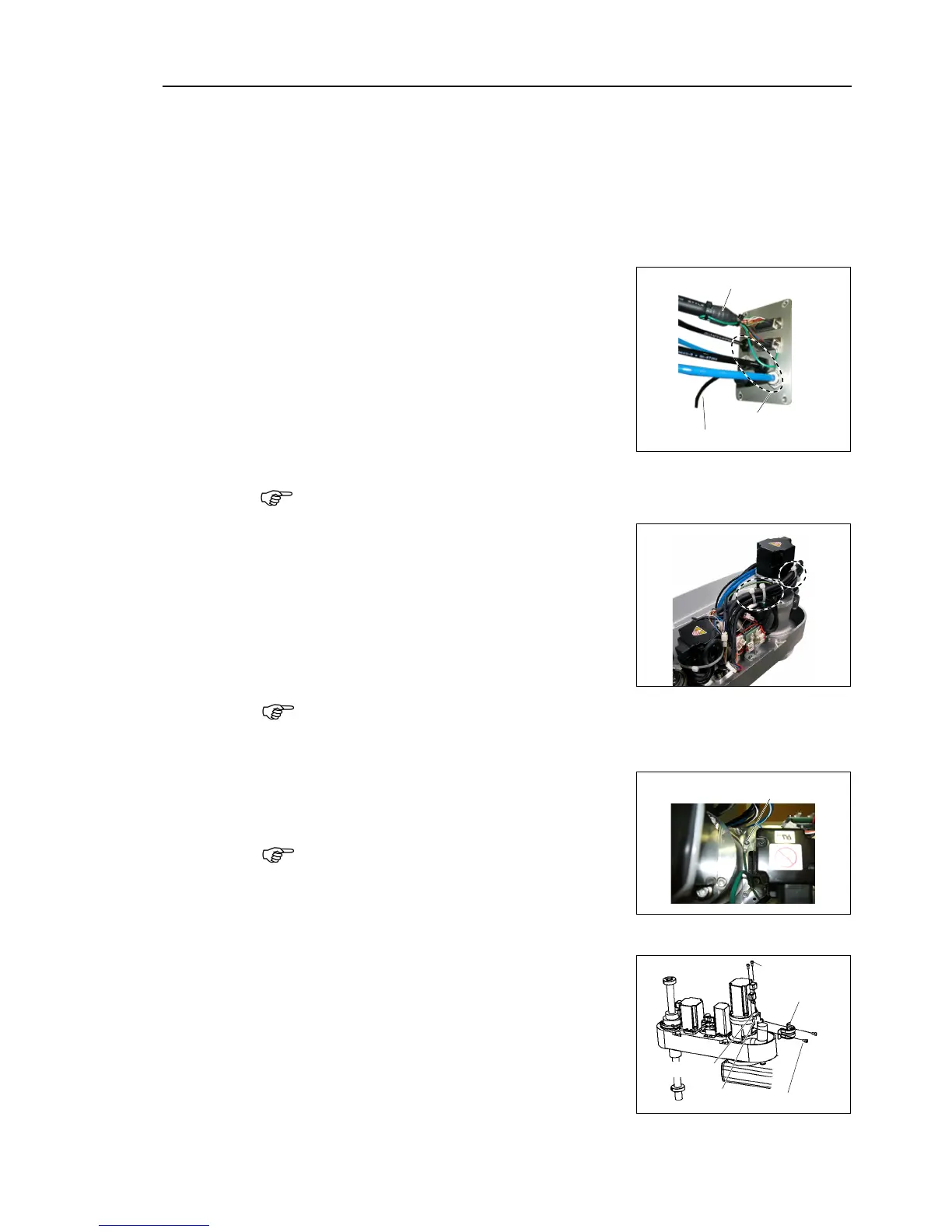
Cut off the wire tie binding cables
the 11 connectors on the Arm side.
X21, X22, X31, X32, X33, X41, X42, X61, X221,
X231, X241
Be sure to keep the connectors excluding X61 of the battery board connected at cables
replacement.
Otherwise, the motor will lose position data and the
calibration must
be executed again.
Remove the ground terminals mounted to Arm
#2
the connection terminal and the
connection point before disconnect the ground
terminal.
G6-***S*, C*: 2 terminals
G6-***D*, P*: 3 terminals
Remove the saddle part mounting cables inside
Arm #2.
s binding cable and fixing