EPSON Stylus C110/C120/D120 Revision B
OPERATING PRINCIPLE Printer Mechanism Operating Principles 28
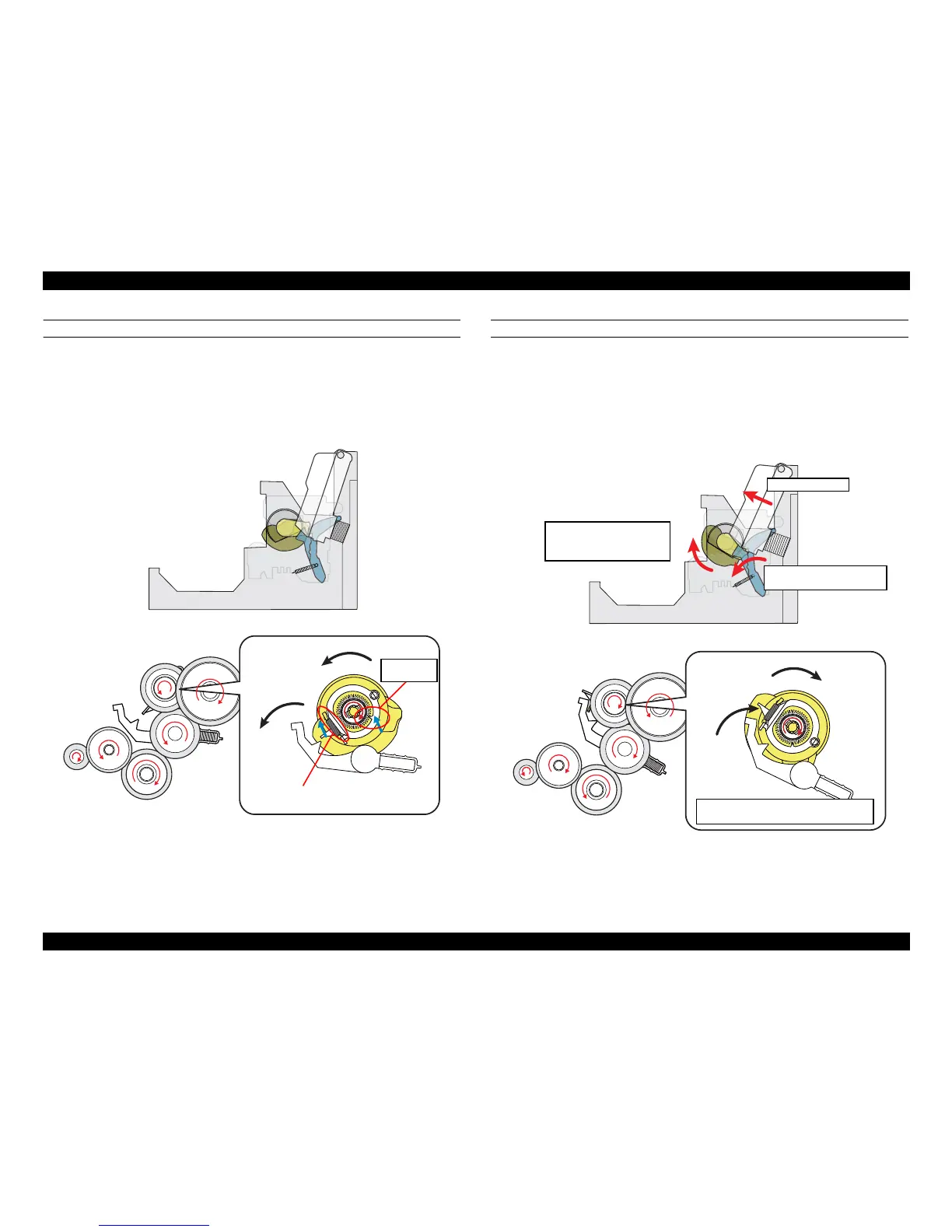
STEP2: RELEASING CLUTCH LEVER TO DRIVE LD ROLLER
When the PF motor pinion gear starts clockwise rotation (as seen from the left side),
the change lever is moved toward the front of the printer to release the clutch lever.
This causes the clutch to engage with the gear by being pulled by the extension spring.
The clutch gear engages with the clutch lock tab and the PF motor drive force is now
can be transmitted to the LD roller shaft.
Figure 2-9. Releasing Clutch Lever
STEP3: FEEDING PAPER FROM ASF
After the engagement of the clutch, the PF motor pinion gear starts counterclockwise
rotation (as seen from the left side) and the drive force is transmitted to the LD roller
shaft via the clutch lock tab and the clutch gear. When the LD roller starts to rotate, the
paper back lever is returned to its standby position, and the hopper is released from the
cams by being pushed by the spring. This causes a sheet of paper to be caught between
the hopper and the LD roller, and the further rotation of the LD roller feeds the paper
into the printer.
Figure 2-10. Feeding Paper from ASF