EPSON Stylus C110/C120/D120 Revision B
DISASSEMBLY/ASSEMBLY Removing Board 78
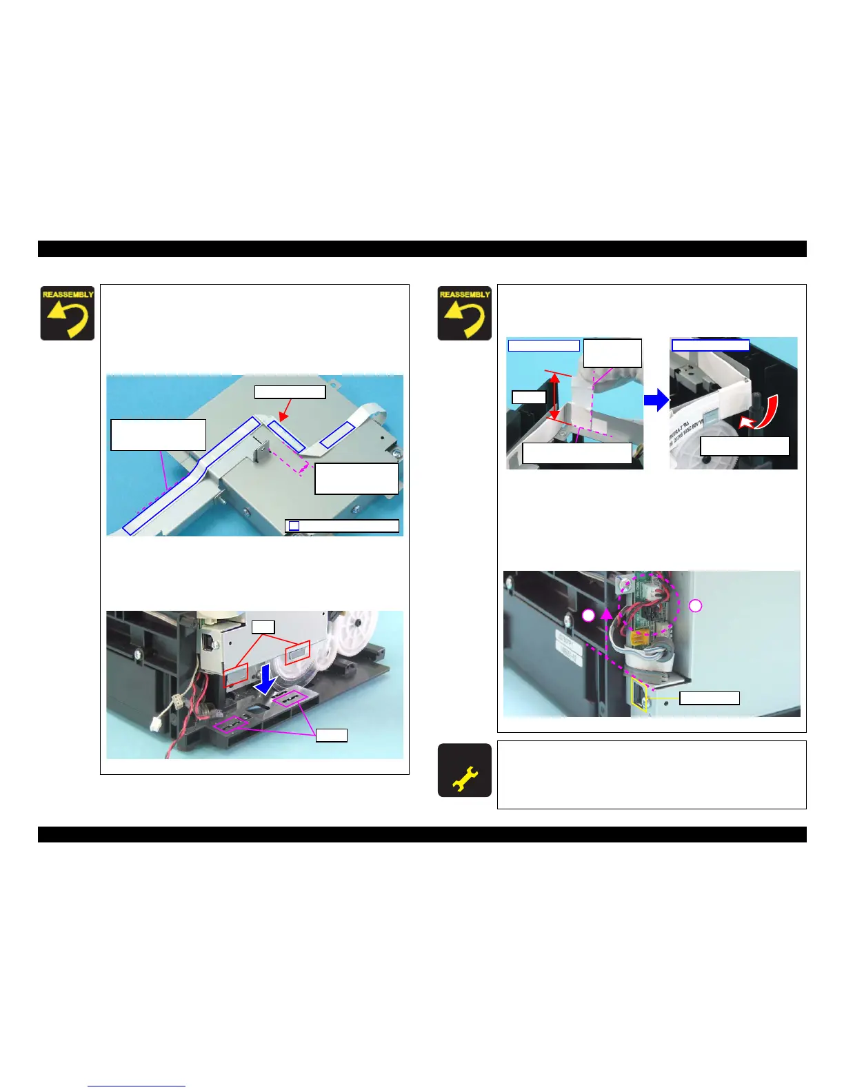
Be careful not to damage the PF Scale and the Spur Gear of
the EJ roller when installing the Main Board Unit and the
Panel Unit.
Route the Panel Unit FFC on the Main Board Unit and the
Panel Unit referring to the figure below. Make sure to fold the
FFC as shown.
Figure 4-14. Routing Panel Unit FFC
When installing the Main Board Unit, be sure to insert the
tabs (x2) of the Main Board Unit into the slots of the Base
Frame (x2).
Figure 4-15. Installing Main Board Unit
9 to 10 mm
(from the slot on the
frame to the tape edge)
Align the edge of the FFC
with the edge of the Left
Frame.
Panel Unit FFC
Double-sided tape position
When routing the Head FFC on the Left Frame, secure the
Head FFC with an acetate tape on the specified position as
shown in the figure below.
Figure 4-16. Acetate Tape Position
Be cautious of the following points when connecting the cables
to the Main Board.
1. Do not let the cables and FFCs over the USB interface.
2. Route the CR Motor cable and the PF Motor cable through the
gap between their connectors.
.
Figure 4-17. Routing cables on the Main Board
A D J U S T M E N T
R E Q U I R E D
After replacing the Main Board Unit, be sure to perform specified
adjustment. See
Chapter 5 “ ADJUSTMENT” (p.107)
50 mm
Align the edge of the tape with
the corner of Left Frame.
Align here with
the cutout of the
Left Frame.
Inside of the frame
Wrap the tape around the
frame and the Head FFC.
Outside of the frame
 Loading...