EPSON Stylus CX4100/CX4200/CX4700/CX4800/DX4200/DX4800/DX4850 Revision A
DISASSEMBLY/ASSEMBLY Removal procedure Specific to the Model With No Card Slot (Stylus CX4100/CX4200/DX4200) 167
4.6 Removal procedure Specific to the Model
With No Card Slot
(Stylus CX4100/CX4200/DX4200)
4.6.1 Printer Mechanism
External view
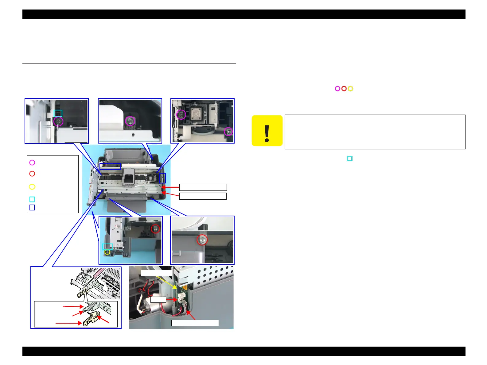
Figure 4-54. Removing Printer Mechanism
Part/Unit that should be removed before removing Printer Mechanism
Document Cover / Paper Support Unit Assy. / Scanner Unit / Panel Unit /
Housing, Upper
Removal procedure
1. Follow the removal procedures Step 1 through Step 3 of
Printer Mechanism (p134).
2. Remove the screws (x7, ) that secure the Printer Mechanism.
3. Disconnect the PS Connector Cable from the connector (CN1) of the Main
Board.
4. Releasing the guide pins (x2, ) of the Front Paper Guide Support and the
Housing, Lower from the groove of the PG Lever with a precision
screwdriver (-), lift up the left side of the Printer Mechanism, and remove the
whole printer mechanism from the Housing, lower.
Front Paper
Guide Support
Guide Pin
Groove
PG Lever
Printer Mechanism
CR Guide Frame
C.B.P. 3x8 F/Zn
(4±1kgfcm)
Guide Pin
Holding Positions
C.B.P. 3x10 F/Zn
(4±1kgfcm)
CN1
Main Board
PS Connector Cable
C.B.S. 3x6 F/Zn
(4±1kgfcm)
C A U T I O N
Hold the designated positions when lifting up the Printer
Mechanism in order to prevent deformation of the Main Frame.
 Loading...


