EPSON Stylus Pro 7400/7800/9400/9800 Revision B
Disassembly & Assembly Disassembly Procedure 232
4.2.4 Removing the Circuit Boards
4.2.4.1 BOARD ASSY., MAIN
1. Remove the Rear Cover. See Section 4.2.3.6 on page 225.
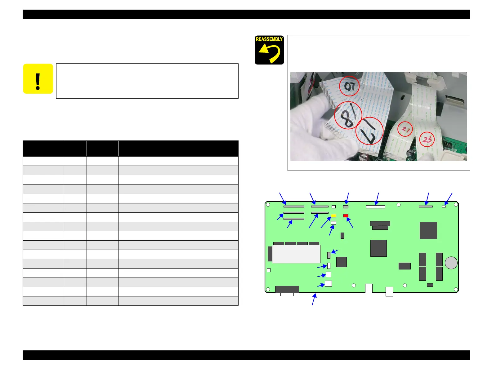
2. Disconnect the following connectors and FFCs from the BOARD ASSY., MAIN.
Figure 4-39. Connector Locations
C A U T I O N
Do not insert FFCs into the connectors at an angle. Doing so may
damage, short, or break the terminals in the connector resulting in
a breakdown of the elements on the board.
Table 4-3. Connectors and FFCs Connected to the BOARD ASSY., MAIN
Connector No. Color
Number of
Pins
Destination
CN1 White 14 P/S BOARD ASSY. (CN001)
CN9 --- 20 PANEL ASSY.
CN10 --- 3 P Rear Sensor
CN13 White 3 Relay harness (CR MOTOR ASSY.)
CN14 White 2 Relay harness (PF MOTOR ASSY.)
CN15 Black 4 Relay harness (Pressure Motor)
CN16 White 4 Relay harness (Pump Motor)
CN17 --- 31 BOARD ASSY., SUB (CN1)
CN18 --- 31 BOARD ASSY., SUB (CN2)
CN20 --- 31 BOARD ASSY., SUB (CN4)
CN21 --- 26 BOARD ASSY., SUB; B (CN1)
CN23 --- 26 BOARD ASSY., SUB; C (CN1)
CN25 Black 3 Relay harness (Right VACUUM FAN ASSY.)
CN26 Red 3 Relay harness (Middle VACUUM FAN ASSY.)
CN27 Yellow 3 Relay harness (Left VACUUM FAN ASSY.)
CN31 White 3 Regulator Solenoid (relay harness)
Connect the FFCs to their correct positions matching the numbers
written on the FFCs with those printed on the board as shown in
Figure 4-39.
CN17, CN18, CN20, CN21, CN23
Figure 4-38. Reconnecting FFCs
CN20 CN21 CN25 CN1 CN9 CN10
CN18
CN17 CN23 CN27
CN31
CN15
CN16
CN14
CN13
CN26
BOARD ASSY., MAIN
 Loading...


