EPSON
TITLE
SHEET
REVISION
NO.
SHEETNEXT
F
TM-U295/U295P
Specification
(STANDARD)
98
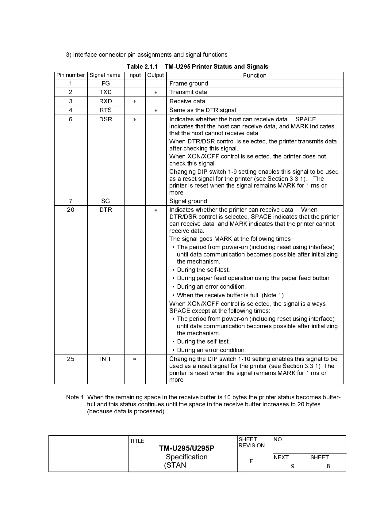
3) Interface connector pin assignments and signal functions
Table 2.1.1 TM-U295 Printer Status and Signals
Pin number Signal name Input Output
Function
1 FG Frame ground
2 TXD
*
Transmit data
3 RXD
*
Receive data
4 RTS
*
Same as the DTR signal
6 DSR
*
Indicates whether the host can receive data. SPACE
indicates that the host can receive data, and MARK indicates
that the host cannot receive data.
When DTR/DSR control is selected, the printer transmits data
after checking this signal.
When XON/XOFF control is selected, the printer does not
check this signal.
Changing DIP switch 1-9 setting enables this signal to be used
as a reset signal for the printer (see Section 3.3.1). The
printer is reset when the signal remains MARK for 1 ms or
more.
7 SG Signal ground
20 DTR
*
Indicates whether the printer can receive data. When
DTR/DSR control is selected, SPACE indicates that the printer
can receive data, and MARK indicates that the printer cannot
receive data.
The signal goes MARK at the following times:
ù
The period from power-on (including reset using interface)
until data communication becomes possible after initializing
the mechanism.
ù
During the self-test.
ù
During paper feed operation using the paper feed button.
ù
During an error condition.
ù
When the receive buffer is full. (Note 1)
When XON/XOFF control is selected, the signal is always
SPACE except at the following times:
ù
The period from power-on (including reset using interface)
until data communication becomes possible after initializing
the mechanism.
ù
During the self-test.
ù
During an error condition.
25 INIT
*
Changing the DIP switch 1-10 setting enables this signal to be
used as a reset signal for the printer (see Section 3.3.1). The
printer is reset when the signal remains MARK for 1 ms or
more.
Note 1 When the remaining space in the receive buffer is 10 bytes the printer status becomes buffer-
full and this status continues until the space in the receive buffer increases to 20 bytes
(because data is processed).